HIgh brightness thermionic cathode

a thermionic cathode, high-brightness technology, applied in the manufacture of discharge tube main electrodes, electrode systems, discharge tube/lamps, etc., can solve the problems of limiting reducing reducing the useful life of the cathode. , to achieve the effect of enhancing the angular intensity and brightness of the electron source, suppressing or eliminating the emission o

Active Publication Date: 2005-08-11
NUFLARE TECH INC
View PDF2 Cites 29 Cited by
  • Summary
  • Abstract
  • Description
  • Claims
  • Application Information

AI Technical Summary

Benefits of technology

[0009] The present invention provides a means to enhance electron source angular intensity and brightness (e.g. in a LaB6 cathode) by greatly suppressing or eliminating cathode cone emission and evaporation. According to the invention, an innovative cathode, a “K-cathode”, which includes a carbon coating applied to the cone surface, is shaped to provide maximum angular intensity and brightness (and thus improved electron beam focusing quality) together with extended cathode lifetime.

Problems solved by technology

The first is that, as the cathode operates, evaporation causes the tip size of the cathode to continuously diminish, limiting the cathode's useful life time.
However, for the tip, which has a much smaller diameter (e.g. 50 microns) a 20 micron loss per side is a major change, resulting in the (100) plane no longer being exposed, and adversely affecting cathode optics and emission
The second major disadvantage of LaB6 cathodes is that, under operating conditions, the electron beam of the cathode is formed by electrons emitted from both the tip and cone surface, as shown in FIG. 4. FIG. 4 shows emitter tip 11 and cone surface 13.
These electrons must be cut off by an aperture stop, which complicates electron beam column design and heat dissipation management, and may lead to high voltage breakdowns.
The prior art has thus far failed to provide a cathode design that results in suppression or elimination of material evaporation and electron emission from the cone surface of LaB6 cathodes.

Method used


Image

  • HIgh brightness thermionic cathode
  • HIgh brightness thermionic cathode
  • HIgh brightness thermionic cathode

Examples


example 1

[0037] Comparison of electron beam angular intensity as a function of total emission current for conventional vs. K-LaB6 cathodes.

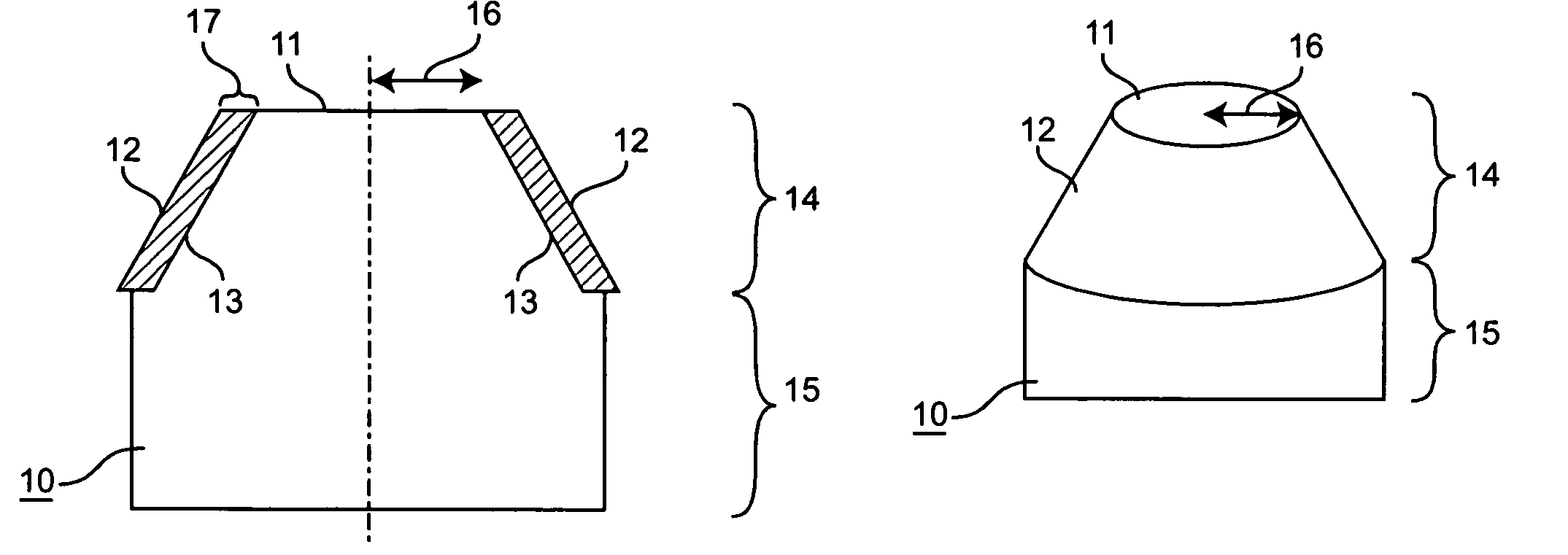
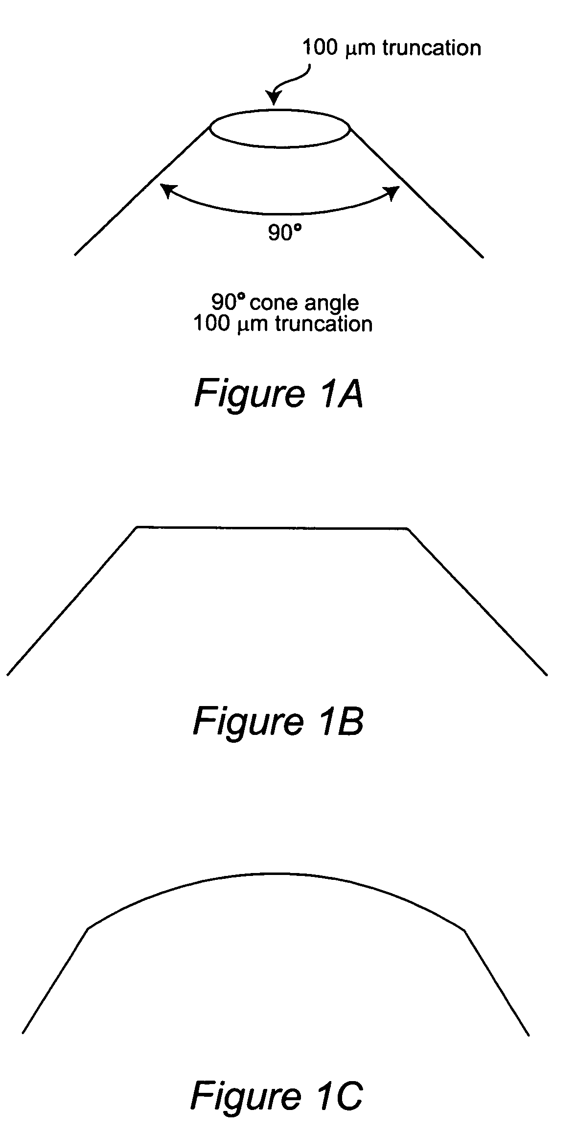
[0038] K-LaB6 cathodes with a coating of carbon applied to the cone surface of the cathode were prepared as follows: regular LaB6 emitters were placed into a chamber filled with carbon-rich gas (propane or butane) and heated up to a specified temperature for several minutes. After that, the emitters were removed from the chamber and the pyrolytic carbon coating formed on the surface was examined. Emitter tips were re-polished to remove carbon from the tips, thus exposing them (see FIG. 7). It was found, for this particular technique, that continuous, pinhole-free carbon coatings were formed with thicknesses ranging from 8 to 10 μm. K-cathodes with angles of 60 degrees and 90 degrees having tips with 50 and 100 μm diameters were fabricated in this manner.

[0039] A comparative study was undertaken in which total electron beam angular intensity as a functio...

example 2

Optimization of Cone Angle in K-LaB6 Cathodes

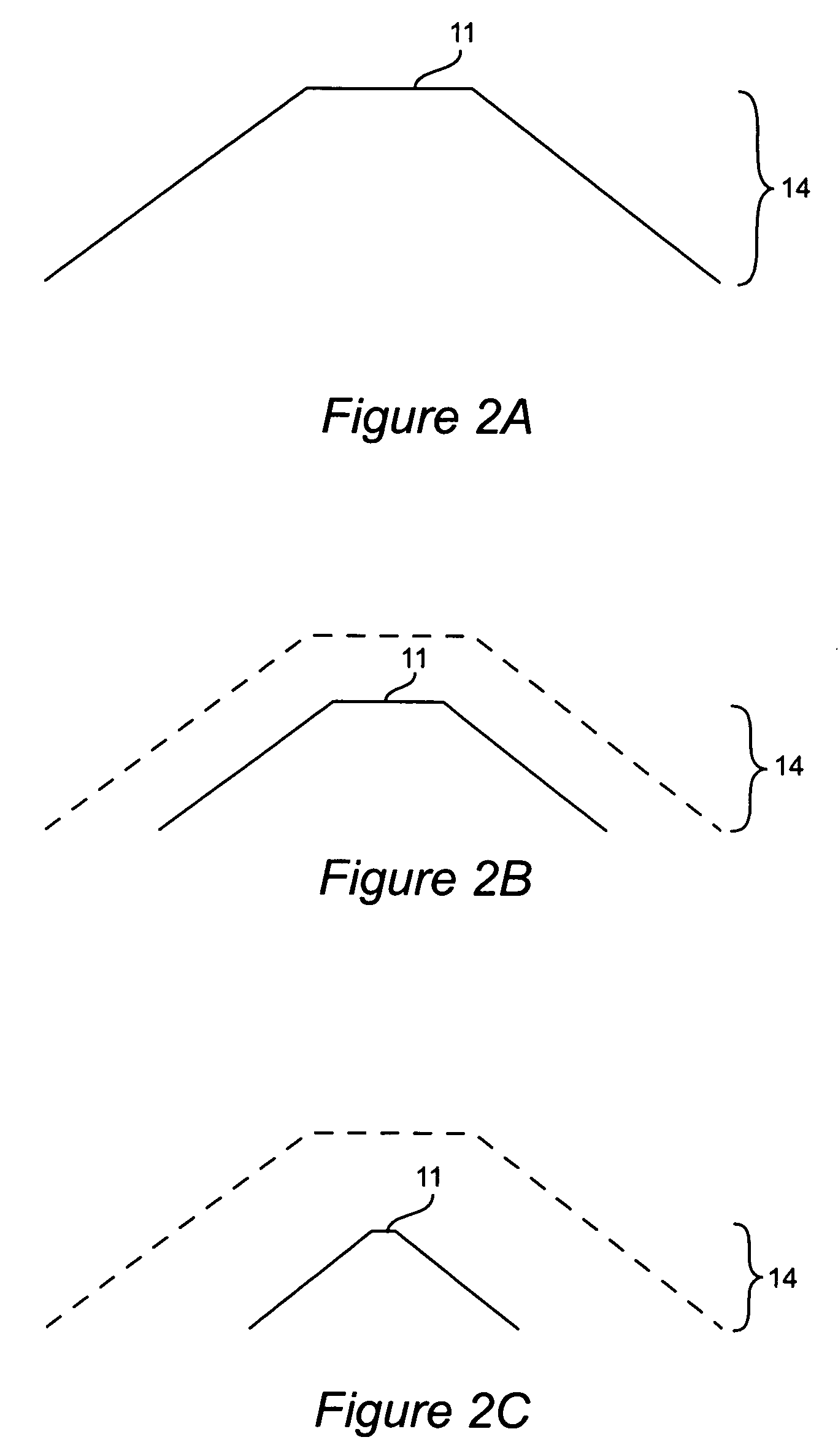
[0041] Further studies were undertaken in order to investigate the effect of varying the cone angle of K-Lab6 cathodes on the lifetime of the cathode. K-LaB6 cathodes having cone angles of 90 and 60 degrees, and tip diameters of 50 μm were utilized. The cone surfaces of the cathodes had a carbon coating of 8 μm which had been deposited in a gas-filled chamber as described above in Example 1.

[0042] The two cathodes were then compared with respect to performance (e.g. percentage emission current and percentage of brightness remaining) before and after extended operation. The results are given in Tables 1 and 2, which show the results obtained with the 90 and 60 degree cone angles, respectively. The columns labeled “Material Loss” show the thickness in μm of LaB6 evaporated from the tip. The columns labeled “% Emission Current” show the percentage of emission current retained. The columns labeled “% Brightness” show percentage of brightne...


PUM


Abstract

An improved thermionic cathode is provided. The cathode has a carbon-coated cone surface and reduced cone angle (e.g. typically 60 degrees or less) that delivers an electron beam with high angular intensity and brightness and exhibits increased longevity.

Description

BACKGROUND OF THE INVENTION [0001] The invention generally relates to an improved thermionic cathode design for use in electron beam lithography tools, scanning electron microscopes, etc. In particular, the invention provides a cathode with a carbon-coated cone surface that delivers an electron beam with high angular intensity and brightness and exhibits increased longevity. BACKGROUND OF THE INVENTION [0002] Single crystal LaB6, or Lanthanum Hexaboride, cathodes are used as the electron source in various electron-beam tools [e.g. lithographic tools, scanning electron microscopes (SEMs), transmission electron microscopes (TEMs), etc.]. A typical LaB6 cathode emitter is tapered, or cone-shaped, with a specified size, cone angle, and tip, or truncation, as shown in the three-dimensional depiction in FIG. 1A. The tip (truncation) may be flat or spherical (as shown in the two-dimensional representations of FIGS. 1B and 1C, respectively), with a diameter ranging from 5 to 100 μm, and a c...

Claims


Application Information

Patent Timeline
Patent Type & Authority Applications(United States)
IPC IPC(8): H01J1/148H01J1/15H01J1/14H01J1/16H01J9/04H01J37/06
CPCH01J1/148H01J1/15H01J2237/06308H01J2201/19H01J9/042
Inventor KATSAP, VICTOR
Owner NUFLARE TECH INC
Why Eureka
Try Eureka