High frequency power amplifier circuit and radio communication system
a power amplifier circuit and radio communication technology, applied in amplifier combinations, gain control, transmission, etc., can solve the problems of increasing the burden on the set maker, difficult to downsize a module, and relatively large power loss, so as to reduce the amount of table data, the effect of lessening the dependency of deviation and reducing the cos
- Summary
- Abstract
- Description
- Claims
- Application Information
AI Technical Summary
Benefits of technology
Problems solved by technology
Method used
Image

Examples
first embodiment
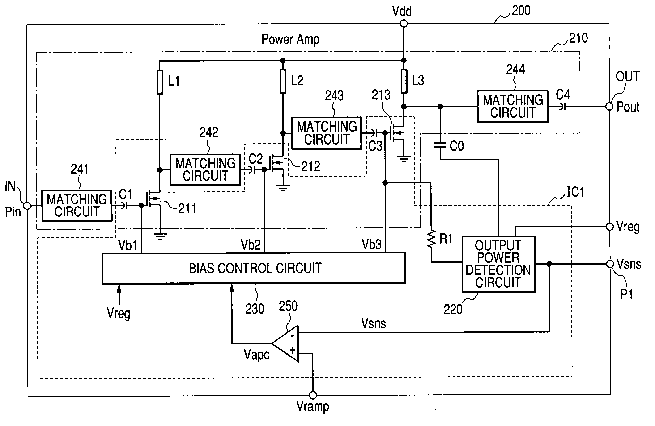
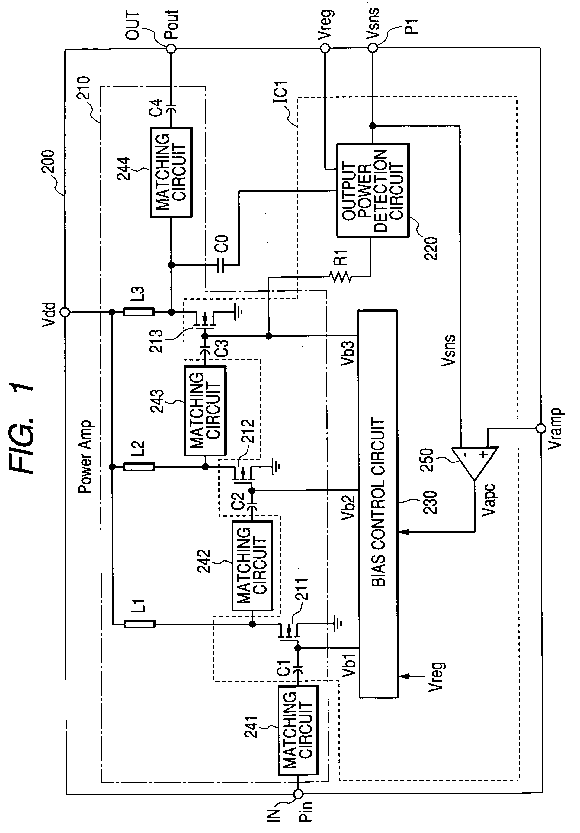
[0043]FIG. 2 is a circuit diagram showing the output power detection circuit 220 of the high frequency power amplifier in FIG. 1, according to a
[0044] The output power detection circuit 220, shown in FIG. 2, comprises a detection transistor Q1 where the voltage identical to the gate voltage of the power amplification FET 213 in the final stage is delivered to the gate terminal thereof via the resistor R1, and current proportional to a drain current of the power amplification FET 213 flows therethrough, a MOS transistor Q2 connected in series to a resistor R2 between the drain terminal of the transistor Q1 and a power source voltage terminal, a MOS transistor Q3 whose gate commonly connected to the gate of the transistor Q2, a square root conversion circuit 221 connected to the drain terminal of the transistor Q3, for converting a drain current flowing in the transistor Q3 into a current Isout equivalent to the square root of the drain current, and a current-voltage conversion resist...
second embodiment
[0055]FIG. 5 shows an output power detection circuit 220 according to the invention.
[0056] The output power detection circuit 220 according to the second embodiment differs from the output power detection circuit 220 according to the first embodiment in that the output power detection circuit 220 according to the second embodiment is provided with a MOS transistor Q4 with a gate terminal on which an AC signal taken but from the drain terminal of the power amplification FET 213 in the final stage via a capacitor C0 is impressed further via a resistor R4, and a drain voltage of the transistor Q4 is impressed on a node N0 interconnecting a drain terminal of a MOS transistor Q2, and a resistor R2 in contrast to the output power detection circuit 220 according to the first embodiment, where the AC signal taken out from the drain terminal of the power amplification FET 213 in the final stage via the capacitor C0 is impressed on the node N0 interconnecting the drain terminal of the MOS tra...
third embodiment
[0064]FIG. 9 shows an output power detection circuit 220 according to the invention.
[0065] The output power detection circuit 220 according to the third embodiment differs from the output power detection circuit 220 according to the second embodiment only in that the AC signal taken out from the drain terminal of the power amplification FET 213 in the final stage via the capacitor C0 is delivered via the resistor R4 to the gate terminal of a current detection MOS transistor Q1 on which a voltage identical to the gate voltage of the power amplification FET 213 in the final stage is impressed, a MOS transistor Q7 with a gate on which the voltage identical to the gate voltage of the power amplification FET 213 in the final stage is impressed via a resistor R7 as with the case of Q1 is provided, and the drain terminal of the MOS transistor Q7 is connected to the drain terminal of the transistor Q3 which is the destination of current mirror transfer. A size ratio of the transistor Q2 to ...
PUM
 Abstract
Description
Claims
Application Information
 - Generate Ideas
- Intellectual Property
- Life Sciences
- Materials
- Tech Scout
- Unparalleled Data Quality
- Higher Quality Content
- 60% Fewer Hallucinations
Browse by: Latest US Patents, China's latest patents, Technical Efficacy Thesaurus, Application Domain, Technology Topic, Popular Technical Reports.
© 2025 PatSnap. All rights reserved.Legal|Privacy policy|Modern Slavery Act Transparency Statement|Sitemap|About US| Contact US: help@patsnap.com