Overcurrent protection for solid state switching system

a solid-state switch and overcurrent protection technology, applied in the direction of dynamo-electric converter control, non-printed jumper connection addition, instruments, etc., can solve the problems of electrical noise and mechanical filament noise, noise incident to phase angle dimming can be unacceptable, and require extensive filtering, so as to improve overcurrent protection and quickly interrupt current flow

Active Publication Date: 2005-08-25
ELECTRONIC THEATRE CONTROLS
View PDF18 Cites 56 Cited by
  • Summary
  • Abstract
  • Description
  • Claims
  • Application Information

AI Technical Summary

Benefits of technology

[0010] A primary object of the present invention is to provide improved overcurrent protection for solid state switching systems such as switching power supplies having high power, high frequency solid state switches. Other objects are to provide overcurrent protection that senses output current directly at the solid state switch and quickly interrupts current flow in response to an overcurrent condition; to provide overcurrent protection that is impervious to transient anomalies;...

Problems solved by technology

With a phase angle dimmer, the abrupt low frequency switching during the half cycles of the power supply and resultant abrupt amplitude changes in the current supplied to a luminaire can cause problems of electrical noise and mechanical filament noise, requiring extensive filtering.
In some dimmer applications, even with filtering, the noise incident to phase angle dimming can be unacceptable.
In addition, phase angle dimmers have the disadvantage that they can reflect harmonic distortion into the mains power supply.
High frequency, high power switches (MOSFETs and IGBTs) used in dimmers and other applications are subject to damage resulting from excess current for even a short period of time.
For example, mistakes in wiring during installation of a dimmer system, or other mishaps, can result in a short circuit or a low resistance circuit across the output of the switching system.
The resulting high current can destroy solid state switches in a very short period of time.
Moreover, defects in the load supplied by the switching system can cause excess currents that, even if smaller than would result from a short circuit, can damage solid st...

Method used


Image

  • Overcurrent protection for solid state switching system
  • Overcurrent protection for solid state switching system
  • Overcurrent protection for solid state switching system

Examples


Embodiment Construction

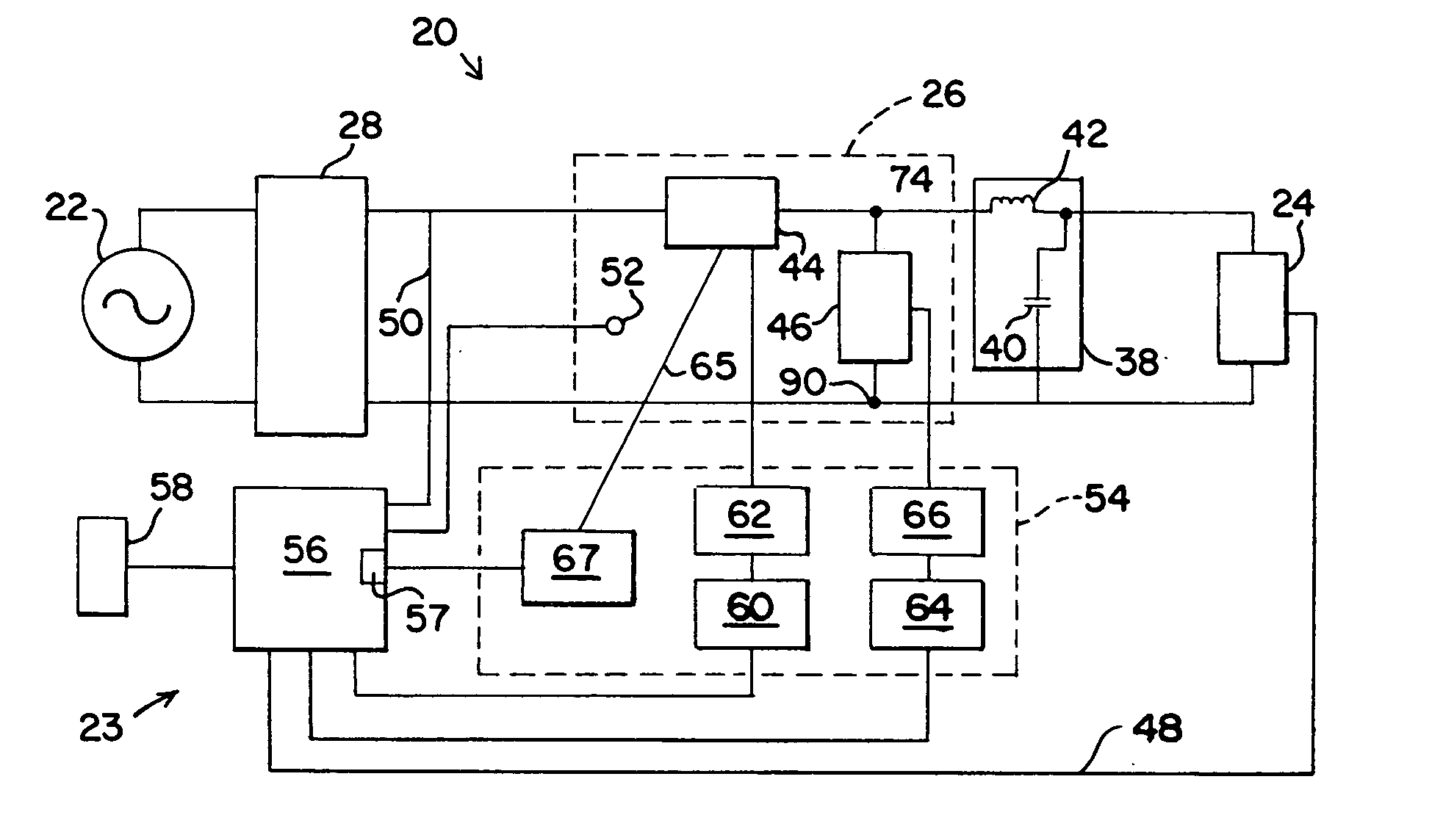
[0024] Having reference now to the drawing, FIG. 1 is a simplified block diagram of a sinewave dimmer designated as a whole by the reference character 20 having a solid state power switching stage 26. In accordance with the present invention, the switching stage 26 is protected by an overcurrent protection system constructed in accordance with the principles of the present invention and generally designated as 23.

[0025] The dimmer 20 is connected to a conventional mains power supply 22 providing a sinusoidal alternating current power supply waveform of, for example, 60 hertz and nominal 120 volts ac. The dimmer 20 provides output power to a load 24. In a typical application, the load 24 may be a resistive load such as an incandescent lamp, or a reactive load such as a power supply for a gas discharge lamp or fluorescent lamp. The power switching stage 26 uses pulse width modulation (PWM) to attenuate input power and supply reduced output power to the load.

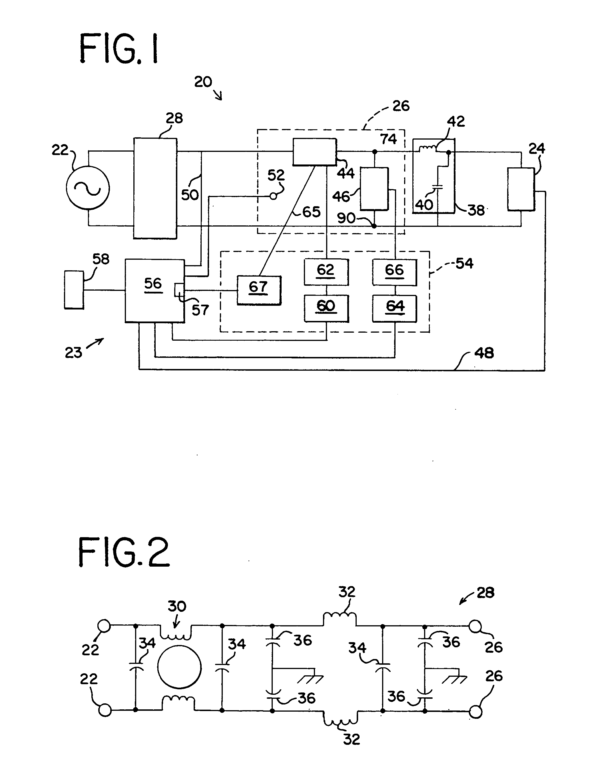
[0026] An input line filt...


PUM


Abstract

Current sensing resistors are connected directly to output terminals of MOSFETs forming the series switching stage of a PWM sinewave dimmer. An analog sensed current signal is coupled through an EMI resistant current link to comparators that provide an overcurrent indication in response to an overcurrent condition. A logic circuit overrides PWM control signals from a programmable controller, and operates drivers to render the series switching stage nonconductive and to render a clamp switching stage conductive until after the end of the current PWM duty cycle power on segment. The logic circuit sends an overcurrent signal through an optocoupler to an input of the programmable controller. The input of the controller is polled at a clock frequency for overcurrent signals and if the count exceeds a limit in any half cycle, or a maximum sum in sixteen half cycles of the AC supply, the series switching stage is rendered nonconductive and the clamp switching stage is rendered conductive pending a reset signal.

Description

CROSS REFERENCE TO RELATED APPLICATION [0001] This is a continuation-in-part of U.S. patent application Ser. No. 10 / 457,067 filed on Jun. 6, 2003, issued on Feb. 1, 2005, as U.S. Pat. No. 6,849,943.FIELD OF THE INVENTION [0002] The present invention relates to active overcurrent protection of solid state switches such as those used for pulse width modulation in sinewave dimmers. DESCRIPTION OF THE PRIOR ART [0003] High frequency, high power solid state switches, namely metal oxide semiconductor field effect transistors (MOSFETs) and insulated gate bipolar transistors (IGBTs), are used in switching systems for switch mode or pulse width modulation (PWM) power supplies. One application for such systems is lamp dimmers. In this application, a lamp is provided with power by a dimmer so that the lamp can be operated at variable, selected light intensity levels. For example, luminaires for theatrical, architectural and other applications are often provided with operating power by dimmers....

Claims


Application Information

Patent Timeline
IPC IPC(8): H02M1/44H02M7/00H05B39/00H05B39/04H05K1/03H05K1/14H05K3/22
CPCH02M1/32H02M1/44H02M5/293H02M2001/0009H05B39/00H05B39/044Y02B20/146H05K1/14H05K1/144H05K3/0061H05K3/222H05K2201/10166H05K1/0306Y02B20/00H02M1/0009
Inventor RASMUSSEN, ERIC G.THURK, JOHN P.SUOMI, ERIC W.
Owner ELECTRONIC THEATRE CONTROLS
Why Eureka
Try Eureka