Hollow-core optical fiber and method of making same

Inactive Publication Date: 2005-08-25
CRYSTAL FIBRE AS
View PDF4 Cites 64 Cited by
  • Summary
  • Abstract
  • Description
  • Claims
  • Application Information

AI Technical Summary

Benefits of technology

[0037] This formula identifies that some metal oxides (such as CaO) have the effect of increasing surface tension in silica and some metal oxides (such as PbO) have the effect of reducing surface tension in silica. The paper describes various methods for measuring the surface tension of glass that could be used to test glasses having different compositions. For example, it would be expected from the formula that adding about 10 mol % Al2O3 to pure silica would increase the surface tension of the glass by about 13%.
[0038] Additionally, adding compounds to silica is expected to reduce the glass transition temperature Tgl. Most preferably, therefore, the surface tension of the glass is increased and the transition temperature is reduced, compared to pure silica, by adding appropriate compounds to the silica. In any event, it is also preferable not to significantly increase bulk loss by varying the composition of the glass. Certainly, adding some compounds, such as FeO, would have this deleterious effect despite having the potential for increasing surface tension, while adding other compounds would not. Of course, it is quite possible that a certain degree of increased bulk loss could be compensated for by the accompanying reduced loss due to capillary wave roughness.
[0039] Considering the third option again, we have found that the mode density of capillary

Problems solved by technology

This degree of loss in HC-PCF clearly represents a problem in, for example, telecoms applications, which often involve propagation of pulses over very long distances.
However, even when comparatively good structural homogeneity is achieved, and light is substantially excluded from solid parts of the fiber, we have discovered that further loss-mechanisms will still undesirably limit the loss performance of HC-PCF.
Surface contaminants on the hole interfaces may lead to absorption or scattering losses directly, or may do so indirectly by acting as centers of formation for microcrystals or for microscopic cracks.
Despite the increase in the material stiffness associated with glass formation, the dynamics and energy balance associated with the glass transition unfortunately do not lead to a reduction of the amplitude of the capillary wave roughness.
A longer perimeter length reduces the strength of the most detrimental spectral components of the roughness.
Certainly, adding some compounds, such as FeO, would have this deleterious effect despite having the potential for increasing surface tension, while adding other compounds wo

Method used


Image

  • Hollow-core optical fiber and method of making same
  • Hollow-core optical fiber and method of making same
  • Hollow-core optical fiber and method of making same

Examples


Embodiment Construction

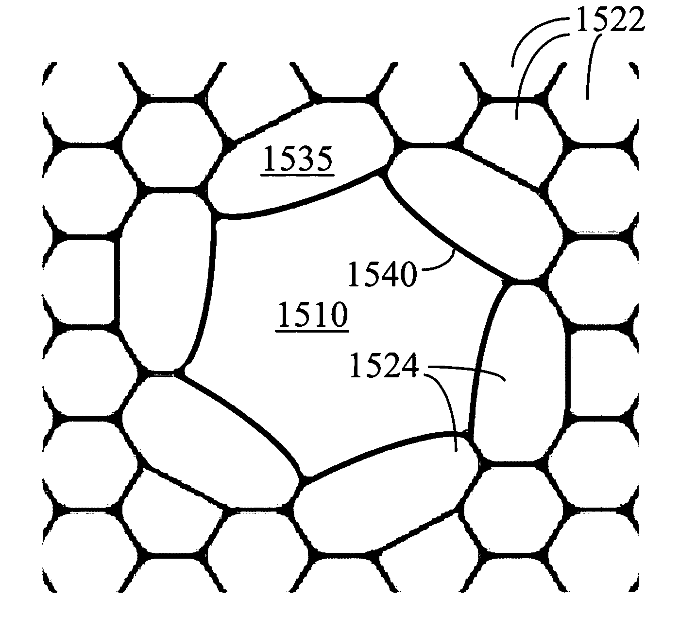
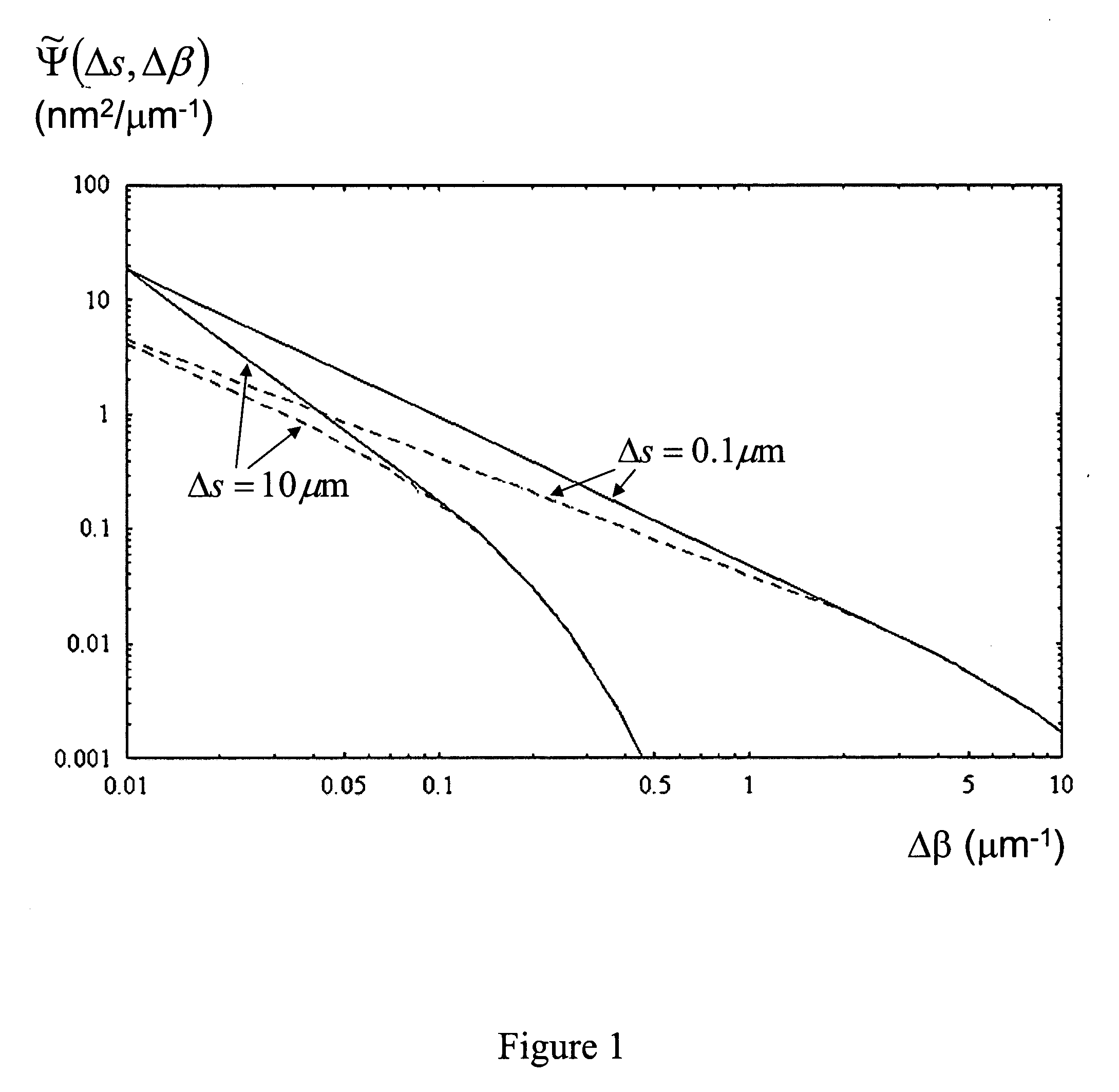
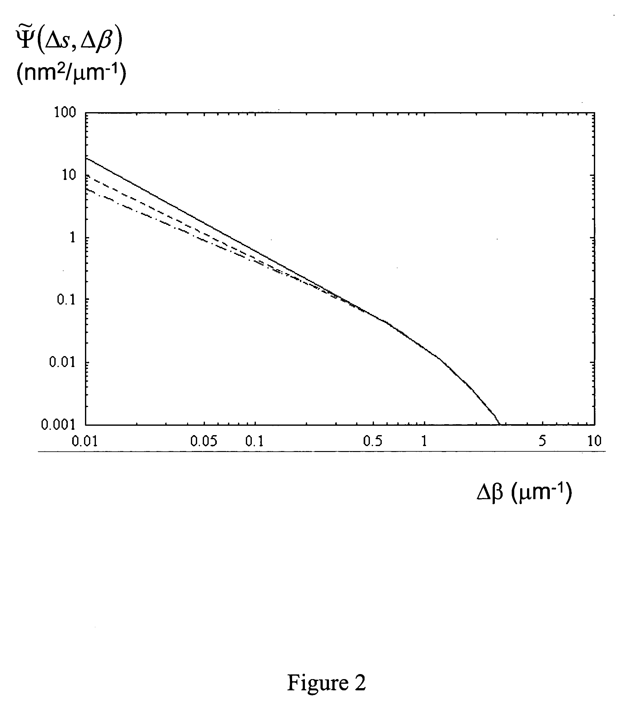
[0097] As already mentioned, HC-PCF contains a multitude of small, closely spaced air holes together with a relatively large central air hole which defines a guiding core. Detailed calculation of the capillary wave roughness spectrum in such complex geometries is a difficult task, and we have used a simplified analysis to predict the effect of varying fiber geometry. Our simplified analysis is validated by comparing the calculated results with measurements taken from real fibers, as will be described hereinafter.

[0098] We find that the mode propagation loss, characterized by an attenuation coefficient γ, incurred from the surface roughness is given by γ1=k34⁢(ɛ0μ0)⁢(ng2-1)2×∑j=1Nholes⁢∮j′⁢th⁢ ⁢holeperimeter⁢ ⁢ⅆs⁢ ⁢∮j′⁢th⁢ ⁢holeperimeter⁢ ⁢ⅆs′⁢ ⁢∫ⅆβ⁢ ⁢e~1,jH⁡(s′)⁢ ⁢Im⁡[G2⁢D⁡(rj+⁡(s′),rj+⁡(s);k,β)]⁢ ⁢e~1,j⁡(s)⁢ ⁢Ψ~j⁡(s,s′;β-β1)(1.1)

where ng is the refractive index of the glass, k=2π / λ is the wave number of the light, ε0 and μ0 are respectively the permittivity and permeability of t...


PUM

PropertyMeasurementUnit
Surface roughnessaaaaaaaaaa

Abstract

An optical fiber having a cladding region surrounding a core region having an elongate core hole, the inner or outer surface of the core hole having a surface roughness with a spatial period equal to or less than 5 μm by a spectral power below 0.0017 nm2μm−1. A method of making an optical fiber including a cladding region having an arrangement of elongate cladding holes in a matrix material, surrounding an elongate core region having an elongate core hole, the method including the step of increasing the surface tension of the matrix material prior to or during the step of heating and drawing the fiber.

Description

CROSS-REFERENCE TO RELATED APPLICATIONS [0001] The present application claims the priority of GB 0403901.2, filed on Feb. 20, 2004, the entire contents of which are incorporated herein by reference. BACKGROUND OF THE INVENTION [0002] 1. Field of the Invention [0003] This invention relates to the field of hollow-core optical fibers, and in particular to the type of fiber known in the art as photonic crystal fiber (PCF), microstructured fiber or holey fiber. [0004] 2. Description of Related Art [0005] Hollow core optical fiber waveguides, which are able to guide light by virtue of a so-called photonic bandgap (PBG), were first considered in 1995. [0006] In, for example, “Full 2-D photonic bandgaps in silica / air structures”, Birks et al., Electronics Letters, 26 Oct. 1995, Vol. 31, No. 22, pp.1941-1942, it was proposed that a PBG may be created in an optical fiber by providing a dielectric cladding structure, which has a refractive index that varies periodically between high and low in...

Claims


Application Information

Patent Timeline
IPC IPC(8): C03B37/012C03B37/014C03B37/016C03B37/027G02B6/02
CPCC03B37/0122G02B6/02347C03B37/01274C03B37/01288C03B37/01446C03B37/016C03B37/02781C03B2201/32C03B2201/54C03B2203/14C03B2203/16C03B2203/42G02B6/02328G02B6/02338C03B37/01231Y02P40/57
Inventor ROBERTS, JOHNSABERT, HENDRIKMANGAN, BRIAN JOSEPHFARR, LANCE
Owner CRYSTAL FIBRE AS
Why Eureka
Try Eureka