
Enhanced hydrogen recovery for hydroprocessing units

a technology of hydroprocessing unit and hydrogen recovery, which is applied in the direction of extraction purification/separation, lighting and heating apparatus, and separation processes, etc., can solve the problems of loss of hydrogen from the system, achieve the effect of maximizing the potential ability of the refinery solvent to remove, enhancing the hydrogen concentration, and reducing the cost of operation and construction

Active Publication Date: 2005-09-01
SAUDI ARABIAN OIL CO
View PDF4 Cites 16 Cited by
  • Summary
  • Abstract
  • Description
  • Claims
  • Application Information

AI Technical Summary

Benefits of technology

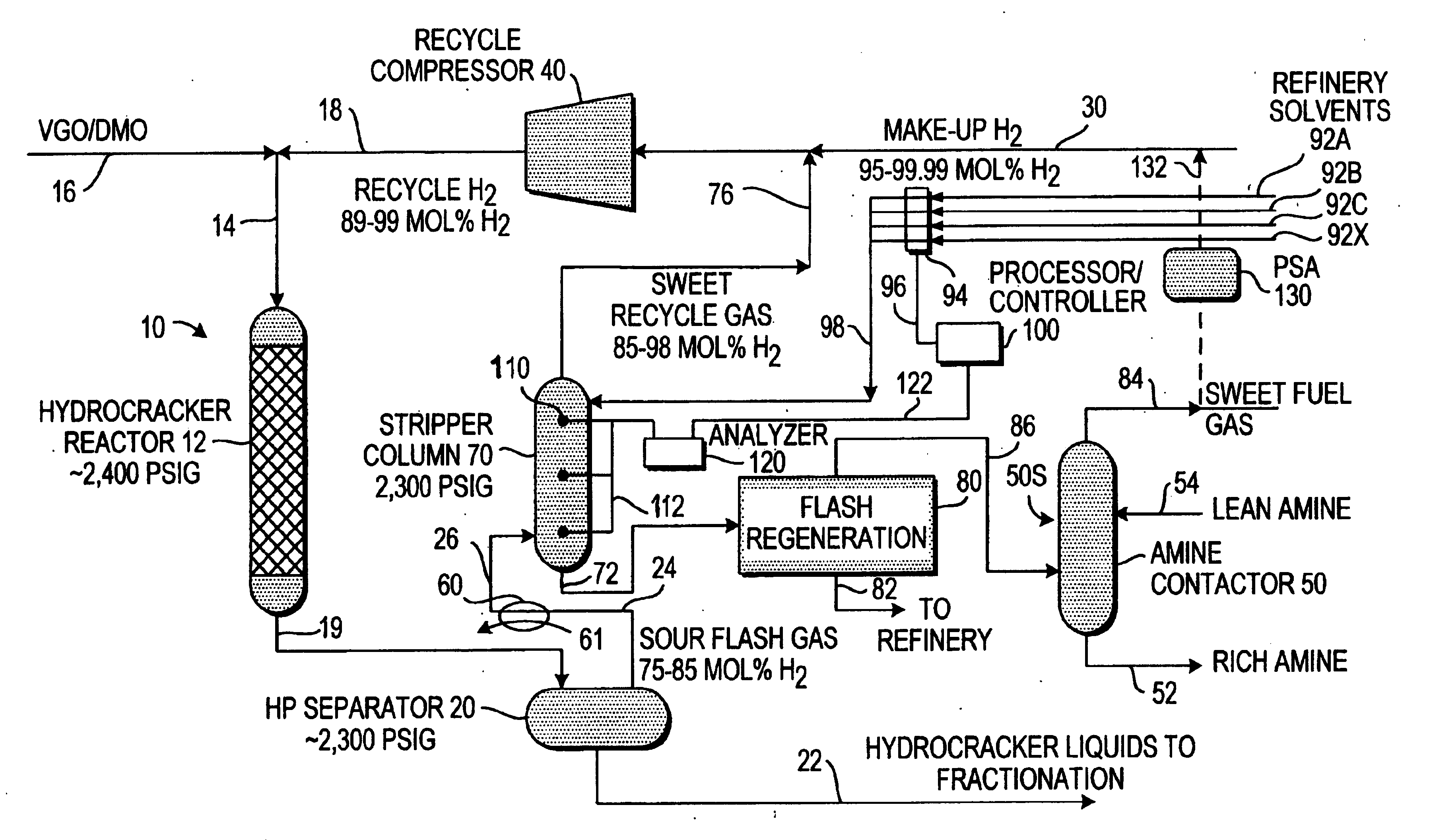
[0010] The above objects and other advantages are obtained by the apparatus and method of the invention in which analytical information on the make-up of the hydrogen-containing feedstream entering the bottom of a stripping column, as well as the composition of the hydrogen recycle stream at and / or approaching the top of the stripping column are provided to a computer-directed control system in real time for the purpose of controlling the selection and the volumetric flow rates of one or more refinery solvents into the column to thereby maximize the removal of non-hydrogen gases from the feedstream and concomitantly maximize the percentage of hydrogen in the recycle gas stream.

Problems solved by technology

The standard approach to this problem by the prior art has been to purge a small portion of the recycle gas stream, which as previously noted, also results in a loss of hydrogen from the system.

Method used


Image

  • Enhanced hydrogen recovery for hydroprocessing units
  • Enhanced hydrogen recovery for hydroprocessing units
  • Enhanced hydrogen recovery for hydroprocessing units

Examples


Embodiment Construction

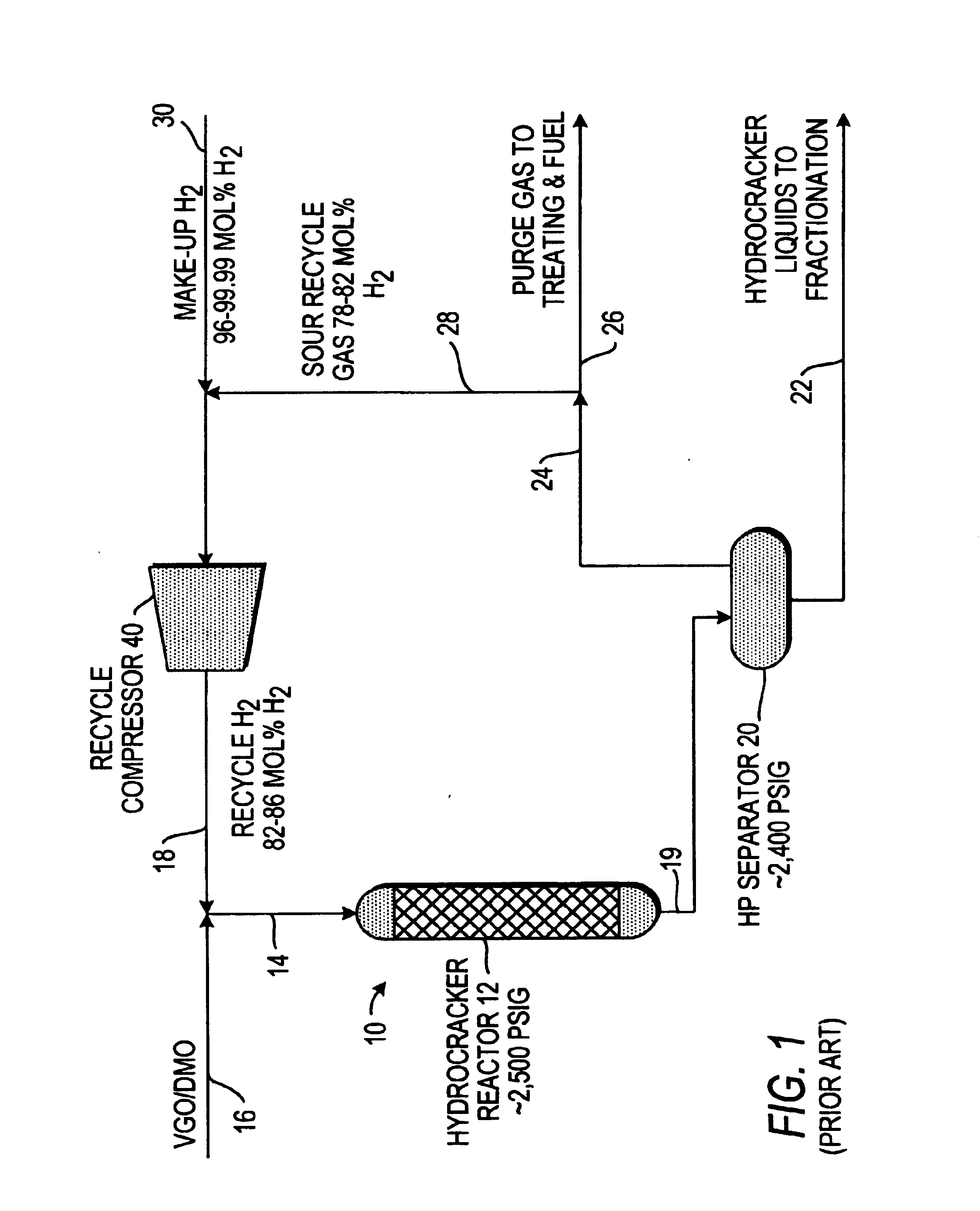
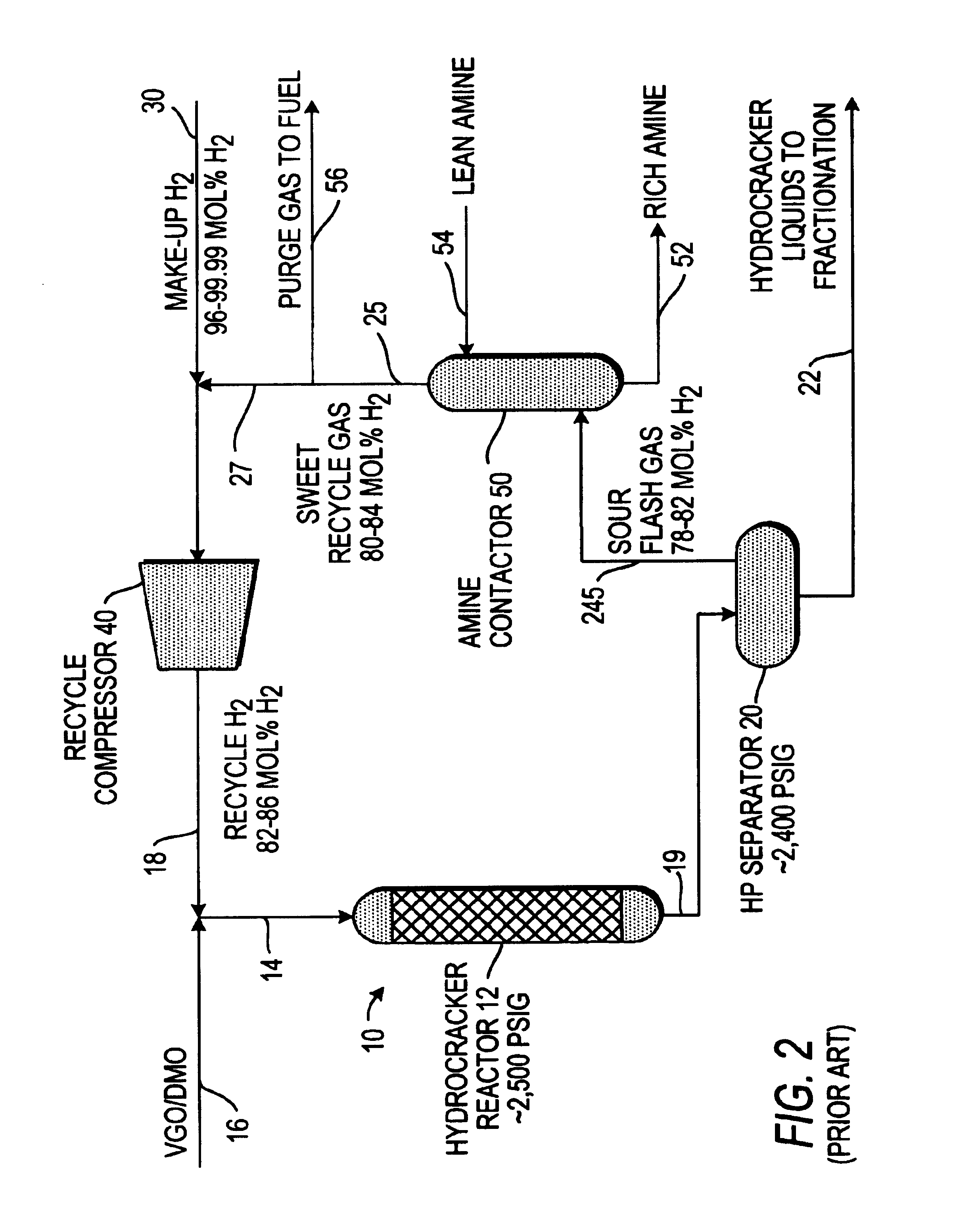
[0036] Since the invention provides a substantial improvement over the processes of the prior art, it is appropriate to describe a typical and representative hydroprocess of the prior art as currently practiced, and to relate its limitations in order to provide an enhanced understanding and appreciation of the advantages of the present invention. In this context, FIGS. 1 and 2 are provided as schematic illustrations of representative prior art hydrocracking units of a type utilized to provide middle distillates, such as jet fuel and diesel fuel.

[0037] As will be understood by those of ordinary skill in the art, various modifications to the process, apparatus, catalysts and operating conditions and steps are possible within the basic elements of the unit operation described. In this regard, a number of competitive hydrocracking technology packages are commercially available from petroleum engineering and refining companies. Many of these commercial processes are proprietary and are ...


PUM

PropertyMeasurementUnit
temperatureaaaaaaaaaa
mol %aaaaaaaaaa
operating pressureaaaaaaaaaa

Abstract

A process for the recovery of high purity hydrogen for recycling to a hydroprocessing or similar unit located in an integrated refinery facility includes sampling and providing analytical information on the make-up of the hydrogen-containing feedstream entering the bottom of a stripping column and the composition of the hydrogen recycle stream at, and / or approaching the top of the stripping column to a computer-directed control system in real time for the purpose of controlling the selection and the volumetric flow rate of one or more “refinery solvents” into the column to maximize the removal of non-hydrogen gases from the feedstream and to thereby maximize the percentage of hydrogen in the recycle gas stream. The “refinery solvent” used in the stripping column is any one or more compounds that are generated as product or by-product streams in the integrated refinery facility that are readily available for diversion in the required quantities for use a solvent to absorb or strip one or more compounds from the hydrogen-containing feedstream at the integrated refinery facility. The refinery solvent is preferable subsequently flashed to remove separated compounds and returned to its original product stream.

Description

FIELD OF THE INVENTION [0001] The invention relates to a method and apparatus for improving the recovery of hydrogen gas from a gaseous process feedstream that also contains methane and other hydrocarbon gases utilizing a liquid solvent in counter-current flow. BACKGROUND OF THE INVENTION [0002] A wide variety of methods and solvents have been disclosed for use in recovering higher yields of hydrogen for recycling in various hydroprocessing treatments. Obtaining a higher yield and purity of hydrogen for a recycled feedstream allows the plant to operate more efficiently and minimize the hydrogen production capacity and therefore the capital required to construct and operate the hydrogen production facility. [0003] It is well known in the art to employ liquid solvents to strip methane, acid gases and other hydrocarbon gases from a mixed process stream containing hydrogen. While it is possible to strip methane and other undesired gases from the stream to leave a relatively high purity ...

Claims


Application Information

Patent Timeline
Patent Type & Authority Applications(United States)
IPC IPC(8): B01D53/14
CPCB01D53/14Y02P20/129
Inventor KHAN, RASHID
Owner SAUDI ARABIAN OIL CO
Learn More