Device for protecting I/O lines using PIN or NIP conducting low capacitance transient voltage suppressors and steering diodes

a low-capacitance transient voltage and diode technology, applied in the direction of electric variable regulation, process and machine control, instruments, etc., can solve the problems of limiting the ability of conventional low-capacitance rectifiers or signal diodes to provide lower capacitance values, and increasing the clamping voltage. , to achieve the effect of improving the capacitance and clamping voltage performance, reducing the clamping voltage, and improving the clamping voltage performan

Active Publication Date: 2005-09-01
BANK OF AMERICA N A
View PDF2 Cites 14 Cited by
  • Summary
  • Abstract
  • Description
  • Claims
  • Application Information

AI Technical Summary

Benefits of technology

[0004] The present invention comprises a circuit arrangement using PIN or NIP diodes for improving the capacitance and clamping voltage performance of conventional low capacitance TVS or steering diodes. The present invention can be implemented in a variety of low capacitance TVSs or steering diodes used for, among other things, protecting higher frequency signal, telecommunication lines and / or wireless communications, or any other high frequency channel or baud-rate line requiring transient protection. The present invention can also be implemented in next generation multimedia systems or network applications and system designs requiring lower capacitance as well as lower clamping voltage performance from conventional TVS or steering diodes. The present invention reduces both capacitance and clamping voltage for transient voltage suppressors or steering diodes used for protecting other sensitive-circuit components. The low capacitance features of the present invention are less sensitive to standby voltages in TVS applications when protecting very high frequency signal lines. The need for lower capacitance values is particularly important for applications operating at higher frequencies or baud rates. Lower clamping voltages are important for protecting components from ESD transients, particularly if the components have low threshold-to-failure voltage levels such as newer generation ICs with smaller features or thinner gates.

Problems solved by technology

However, conventional low-capacitance rectifiers or signal diodes are limited in their ability to provide lower capacitance values without also significantly increasing their clamping voltage (VC).
Consequently, newer generation integrated circuits (“ICs”) and CMOS devices are more vulnerable to transients, including electrostatic discharge (“ESD”).
Conventional low capacitance rectifiers or signal diodes do not provide both low capacitance values and low clamping voltages.
Conventional low-capacitance rectifiers or signal diodes in series with a TVS element or as individual steering diodes have disadvantages when used in telecommunications and other applications that operate at higher frequencies using sensitive ICs or CMOS components requiring lower voltage levels.

Method used


Image

  • Device for protecting I/O lines using PIN or NIP conducting low capacitance transient voltage suppressors and steering diodes
  • Device for protecting I/O lines using PIN or NIP conducting low capacitance transient voltage suppressors and steering diodes
  • Device for protecting I/O lines using PIN or NIP conducting low capacitance transient voltage suppressors and steering diodes

Examples


first embodiment

[0046]FIG. 9, being the present invention, is a schematic of a unidirectional blocking low capacitance TVS using a PIN or NIP diode. As seen therein, a TVS p-n junction diode element 901 and low-capacitance (“LC”) diode PIN or NIP junction element 902 are placed in series and with opposite polarity for unidirectional protection. The unidirectional low capacitance TVS component 900 is a two (2) terminal device that has at least one unidirectional TVS element 901 and one series blocking PIN or NIP junction diode 902, in opposite polarity for reducing capacitance in one direction only.

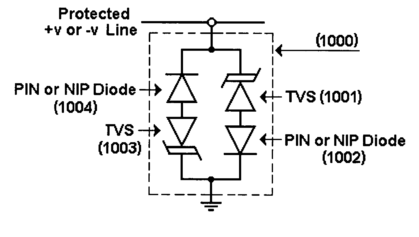
[0047]FIG. 10, being a second embodiment of the present invention, is a schematic of the bi-directional low capacitance TVS using a PIN or NIP diode. Bi-directional low capacitance TVS protection circuit 1000 consists of two pairs of TVS diodes 1001, 1003 and LC PIN or NIP diodes 1002, 1004. Diodes 1003 and 1004 are in parallel and in opposite direction from the first series of TVS and LC diode pair shown...

third embodiment

[0048]FIG. 11, being the present invention, is a schematic of the unidirectional conducting low capacitance TVS using a PIN or NIP diode. TVS circuit 1100 is adapted to provide unidirectional conducting, low capacitance protection. Circuit 1100 comprises an LC PIN or NIP diode 1103 in parallel to the TVS diode 1101 and LC PIN or NIP diode 1102, and opposite direction of the LC PIN or NIP diode 1102. This configuration provides a low-voltage, conduction path in one direction in parallel with a low-capacitance diode and unidirectional TVS protection as seen in FIG. 1A. The circuit of FIG. 11, discloses a two (2) terminal device with a unidirectional low capacitance TVS diode 1101 as described in FIG. 9 and an anti-parallel LC PIN or NIP diode 1102. To provide for a low capacitance TVS with a forward conducting low-voltage characteristic, the LC PIN or NIP diode is placed anti-parallel to the unidirectional low capacitance TVS. This LC PIN or NIP diode must also have a reverse blocking...


PUM


Abstract

A device for protecting I/O lines using low capacitance steering diodes (1200) and PIN or NIP diodes (1202), (1203) is disclosed. A low capacitance diode arrangement configured as steering diodes protect a signal line or input/output (I/O) port (1201) from high voltage transients by diverting or directing the transient to either the positive side of the power supply line (1204) or to ground (1205).

Description

CROSS REFERENCE TO RELATED APPLICATIONS; CLAIMS OF PRIORITY [0001] This application is a divisional of U.S. patent application Ser. No. 10 / 788,536, filed Feb. 27, 2004 entitled “PIN or NIP Low Capacitance Transient Voltage Suppressors and Steering Diodes”, the entire contents of which are incorporated herein by this reference. The Applicant hereby claim the benefits of this pending patent application under 35 U.S.C. Section 119(e).FIELD OF THE INVENTION [0002] The present invention relates to low capacitance transient voltage suppressors (“TVSs”) or steering diodes used for protecting high frequency signal channels, including telecommunication lines, wireless communications, and high baud-rate lines. BACKGROUND OF THE INVENTION [0003] For optimum transient protection of sensitive devices that operate at high frequencies, low capacitance rectifiers or signal diodes are needed. Lower capacitance values are required to minimize or eliminate signal distortion at higher frequencies. Howe...

Claims


Application Information

Patent Timeline
Patent Type & Authority Applications(United States)
IPC IPC(8): H01L29/868H01L29/93H02H9/00H02H9/06H02M3/335
CPCH01L29/868Y02E10/548
Inventor WALTERS, CECIL KENT
Owner BANK OF AMERICA N A
Why Eureka
Try Eureka