Charged device, cleaning device, process cartridge, toner, and image-forming device that uses these

a technology of image-forming device and charge device, which is applied in the direction of electrographic process apparatus, discharge of corona, instruments, etc., can solve the problems of image quality decline, charging characteristics can deteriorate, and charge characteristics can deteriorate, so as to prevent the image quality from deteriorating, increase the cost, and prevent the effect of the charged state deteriorating

Active Publication Date: 2005-09-01
RICOH KK
View PDF7 Cites 65 Cited by
  • Summary
  • Abstract
  • Description
  • Claims
  • Application Information

AI Technical Summary

Benefits of technology

[0026] A first object of the present invention is to solve the first problem described above, and particularly in view of the cleaning problems of the charged device, an object is to provide a cleaning device that has a configuration cap...

Problems solved by technology

There are drawbacks in a charged device that uses the non-contact method in that ozone, nitrogen oxide, and other corona products associated with corona discharge cause adverse environmental effects, and the charging characteristics can deteriorate when nitric compounds (ammonium nitrate) and other discharge products based on nitrogen oxide are deposited.
When the surface of the image carrier is cut by the etching phenomenon produced by the charged roller, a film-thinning phenomenon is created whereby the film thickness of the photosensitive layer of the surface thereof is reduced, and it is possible that the charging characteristics may deteriorate and the image quality may decline as these phenomena occur.
There is an additional problem in that the charged roller becomes soiled, which is another reason that the image quality may decline due to the deterioration of the charging characteristics of the image carrier when a charged roller is used.
For this reason, the surface friction changes when partial soiling occurs on the charged roller, and, as a result, a homogeneous charge cannot be imparted to the image carrier.
Considering the soiling problems of such a charged roller, the film thinning of the latent image carrier can be reduced in the method for applying DC voltage exclusively to the charged roller as described above, but partial soiling tends to occur in that toner, paper dust, and other unwanted matter is deposited on the surface of the charged roller, and, as a result, the electrical resistance on the surface thereof may become nonuniform.
When the uniform charge on the image carrier is degraded, a slight variation in the friction causes image smudges or nonuniformity in the image because AC voltage cannot be applied.
For this reason, the charged device configuration becomes more complicated, resulting in higher costs.
When a cleaning member in the form of a pad or a sponge is used, the captured foreign matter must be retained, but it is difficult to retain the foreign matter simply by bringing the cleaning member into contact with the charged roller.
For this reason, when a cleaning structure is provided to the charged roller in either case, a mechanism for capturing foreign matter and a recovery mechanism is required in addition to the charged roller and cleaning structure, and higher costs due to the greater size and complexity of the device are unavoidable.
Such drawbacks are not limited to charged devices that simply use a charged roller, but also apply to transfer devices and other devices that may involve contact with the latent image carrier.
However, the above-described toners with smaller, spherical-shaped particles tend to slide on the cleaning blade in the cleaning step, and cleaning tends to be inadequate.
In other words, residual toner on the surface of the image carrier adheres...

Method used


Image

  • Charged device, cleaning device, process cartridge, toner, and image-forming device that uses these
  • Charged device, cleaning device, process cartridge, toner, and image-forming device that uses these
  • Charged device, cleaning device, process cartridge, toner, and image-forming device that uses these

Examples


first embodiment

[0065] The present embodiment is designed to achieve the first object of the present invention described above.

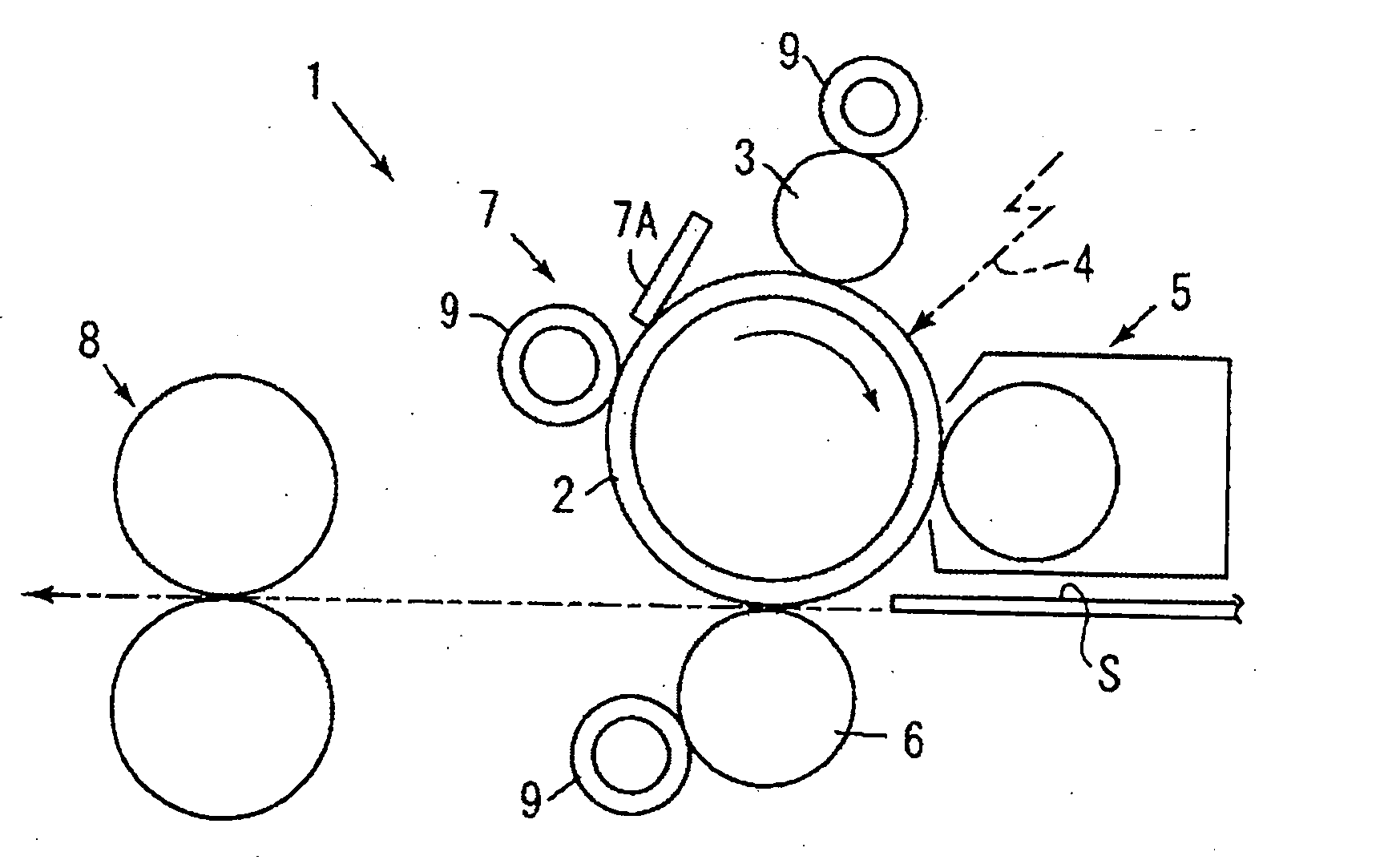
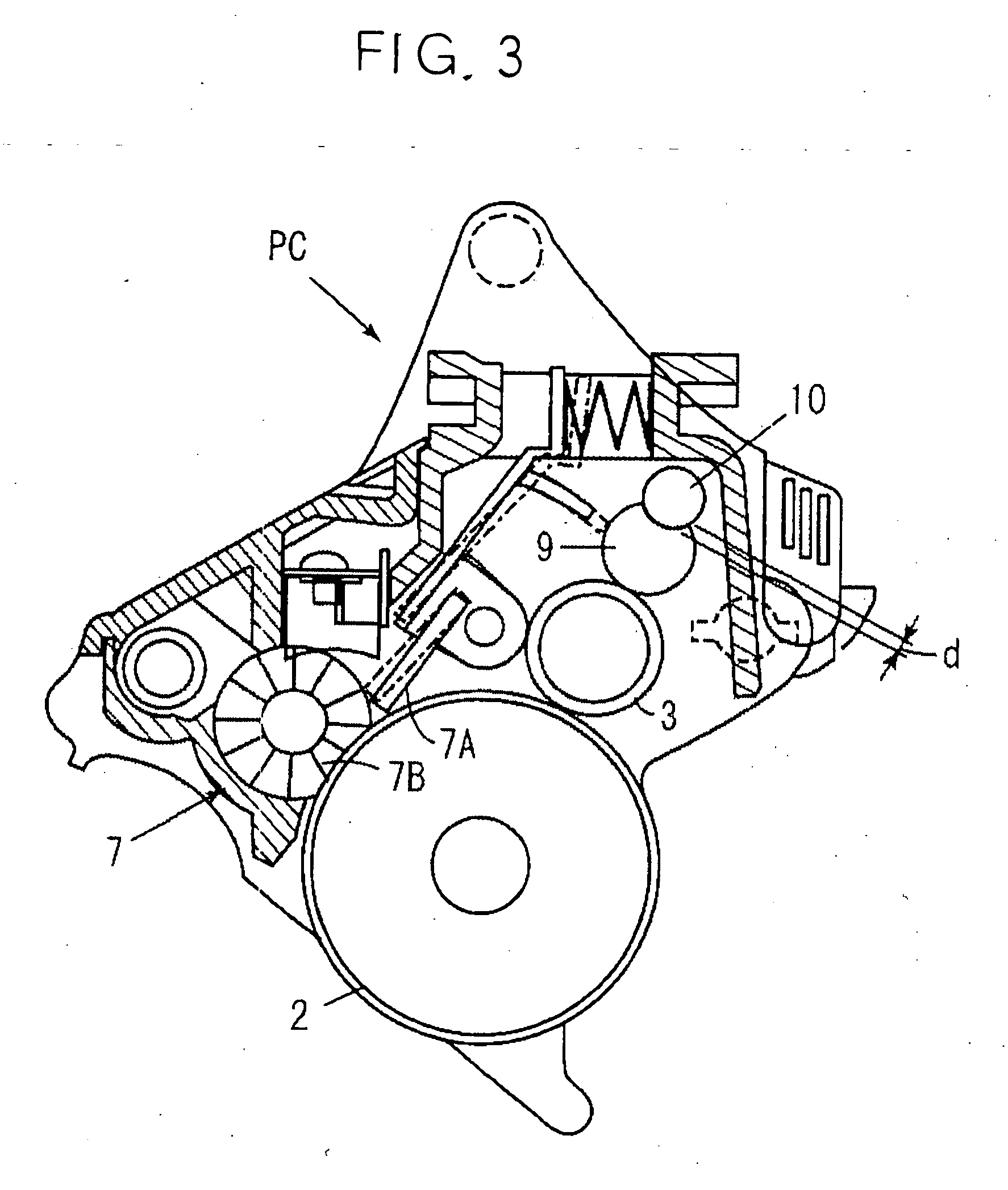
[0066]FIG. 1 shows the configuration of an image-forming device in which the cleaning device according to the present embodiment has been applied, and the image-forming device 1 shown in the diagram is provided with a photoreceptor 2 in the form of a drum (hereinafter referred to as “photoreceptor drum”) as a latent image carrier. Disposed around the photoreceptor drum 2 are a charged device 3 for carrying out an image formation routine along the direction of rotation (direction of the arrow in the diagram) of the drum 2, a writing device (only the optical path is shown) 4, a developing device 5, a transfer device 6, and a cleaning device 7.

[0067] In the image-forming device 1 shown in FIG. 1, a uniform charge is created by the charged device 3 during the rotation of the photoreceptor drum 2, an electrostatic latent image is then formed by the writing device 4 in correspo...

second embodiment

[0099]FIG. 4 is a diagram showing the general configuration of the first concrete example of the image-forming device according to the present embodiment, and FIG. 5 is a diagram showing the general configuration of the photoreceptor unit.

[0100] The image-forming device is provided with four image-forming units 1Y, 1M, 1C, and 1K for forming images in each of the colors yellow (Y), magenta (M), cyan (C), and black (K). Is should be noted that the sequence of the colors Y, M, C, and K is not limited to FIG. 1, and other color sequences are possible.

[0101] The image-forming units 1Y, 1M, 1C, and 1K are provided with photoreceptor drums 11Y, 11M, 11C, and 11K, respectively, as image carriers, as well as with a charged device, a developing device, and a cleaning device. Also, the image-forming units 1Y, 1M, 1C, and 1K are arranged so as to be parallel to the axis of rotation of the photoreceptor drum and be arrayed at a prescribed pitch in the movement direction of the transfer paper....

third embodiment

[0201] Described below is an embodiment in which the present invention has been applied to a color laser printer (hereinafter simply referred to as “printer”), which is an image-forming device.

[0202]FIG. 15 is a diagram of the general configuration of the printer according to the present embodiment. The printer is configured with a tandem image-forming unit in which four image-forming devices for the colors yellow, cyan, magenta, and black are aligned in a lateral arrangement. In the tandem image-forming units, the image-forming devices 101Y, 101C, 101M, and 101K, which are each toner image-forming devices, are disposed in order from the left side of the diagram. Here, each of the subscripts of the key symbols Y, C, M, and K represent members for yellow, magenta, cyan, and black, respectively. In the tandem image-forming device unit, the image-forming devices 101Y, C, M, and K are provided with a charged device, developing devices 10Y, C, M, and K, a photoreceptor cleaning device, ...


PUM


Abstract

There is provided a cleaning device for an image-forming device configured so as to be capable of preventing the image quality from deteriorating by being able to prevent the deterioration of the charging state caused by deposits of foreign matter without increasing costs. There is also provided a cleaning member that can make contact with the cleaning target-members. The cleaning member has a portion composed of melamine resin foam for making contact with at least the cleaning target members, and the melamine resin foam has an Asker F hardness of 5 to 25 points and a hardness variation of 5 points or less, and is used on the cleaning target members in a state obtained by heat compression from the original shape. The pressing member is furthermore disposed in contact with the cleaning member.

Description

BACKGROUND OF THE INVENTION [0001] 1. Field of the Invention [0002] The present invention relates to copiers, printers, facsimile devices, and other image-forming devices for forming images with electrophotography, and a charged device, cleaning device, process cartridge, and toner that are adopted therein. [0003] 2. Description of the Background Art [0004] In this type of electrophotographic image-forming device, a charge with a prescribed polarity is imparted and retained by discharging electricity on the surface of a photoreceptor or other image carrier, the charged photoreceptor surface is exposed to form an electrostatic latent image, toner charged with the same polarity as the charged polarity is fed to the electrostatic latent image, and a toner image is formed. The toner image formed on the surface of the image carrier is transferred to recording paper or another medium, and heat and pressure are applied to fix the image to the recording paper or other medium. Also, since th...

Claims


Application Information

Patent Timeline
IPC IPC(8): G03G15/02
CPCG03G15/0225
Inventor MURAISHI, TAKAYANINOMIYA, HIROMICHISAMPE, ATSUSHIKIMURA, YOSHIYUKINAGASHIMA, HIROYUKIHOSOKAWA, HIROSHIAMEMIYA, KENKOIKE, TOSHIOOJIMI, TOKUYATAWADA, TAKAAKISHINTANI, TAKESHIARAI, YUJIYONEDA, TAKUJIKAWASUMI, MASANORITOMITA, MASAMI
Owner RICOH KK
Why Eureka
Try Eureka