Heat exchanger having plural tubular arrays

a technology of heat exchangers and tubular arrays, which is applied in the direction of indirect heat exchangers, lighting and heating apparatus, energy input, etc., can solve the problems of large stress on baffles and pan ductwork, premature failure, and insufficient heat exchanger stage area, so as to facilitate accurate dynamic control of process temperature and reduce pressure inside the heat exchanger , the effect of improving heat recovery

Inactive Publication Date: 2005-09-08
LAIR LIQUIDE SA POUR LETUDE & LEXPLOITATION DES PROCEDES GEORGES CLAUDE
View PDF15 Cites 49 Cited by
  • Summary
  • Abstract
  • Description
  • Claims
  • Application Information

AI Technical Summary

Benefits of technology

[0011] The present invention also advantageously provides a bottom module including the housing and first fluid passageway, and a top module having an additional fluid passageway extending therethrough and including a superheater section, a boiler section, and a preheater section. The top and bottom module and the fluid passageways therein have a vertical arrangement that advantageously utilizes buoyancy of heated fluid flowing through the passageways in order to create a natural draft through the top and bottom modules, thereby reducing pressure inside the heat exchanger. Ideally, a vacuum is attained inside the reformer housing. This effect can also be supplemented with the addition of an exhaust fan.
[0012] The present invention also provides an air diverting means and a method of use to facilitate accurate dynamic control of the process temperatures during all operating modes. The present invention also provides a heat recovery air preheater that may be closely mechanically-integrated into the reactor of the present invention or the reactor of the '856 patent to facilitate improved heat recovery when compared to the process of the '719 patent. A method of operating the improved heat recovery means either independently, or more preferably in conjunction with the air diverting means is also provided.

Problems solved by technology

Since the reformers tend to operate under high thermal stress, as the reactor is scaled up in size, a high pressure drop (i.e., change in pressure, ΔP) across the tube array can put large stresses on the baffles and the pan ductwork.
These large stresses lead to premature failure due to creep at services temperatures.
Thus, simply increasing the heat exchanger stage area does not provide an adequate solution.
Additionally, when the reactor is scaled up in size, the overhanging burner box is plagued by high stresses, due to the large size of the pans and due to the cantilever forces from the burner.
Furthermore, very big reactors require very thick tubesheets.
These thick, beefy tubesheets are not only expensive, but they are also very rigid.
Such large through-holes limit the effectiveness of the reformer by causing bypassing of the tube arrays.
In the manufacture of hydrogen, and especially in the manufacture of hydrogen according to the process of U.S. Pat. No. 6,623,719 (the '719 patent) wherein the combustion air is preheated in the cooling of the water gas shift process, the simultaneous control of the flame temperature, water gas shift process temperature and steam reformer inlet temperatures can be extremely difficult.
Departure from the preferred temperature conditions can cause poor fuel conversion, high thermal stresses, excessive corrosion, and problems with local condensing and reboiling of steam within the system.
These deficiencies are particularly problematic during transient operation, such as startup, shutdown and load changes.
This wasted heat energy undesirably increases the operating cost of the hydrogen process and increases emissions of climate change gases.

Method used


Image

  • Heat exchanger having plural tubular arrays
  • Heat exchanger having plural tubular arrays
  • Heat exchanger having plural tubular arrays

Examples


Embodiment Construction

[0023] Embodiments of the present invention will be described hereinafter with reference to the accompanying drawings. In the following description, the constituent elements having substantially the same function and arrangement are denoted by the same reference numerals, and repetitive descriptions will be made only when necessary.

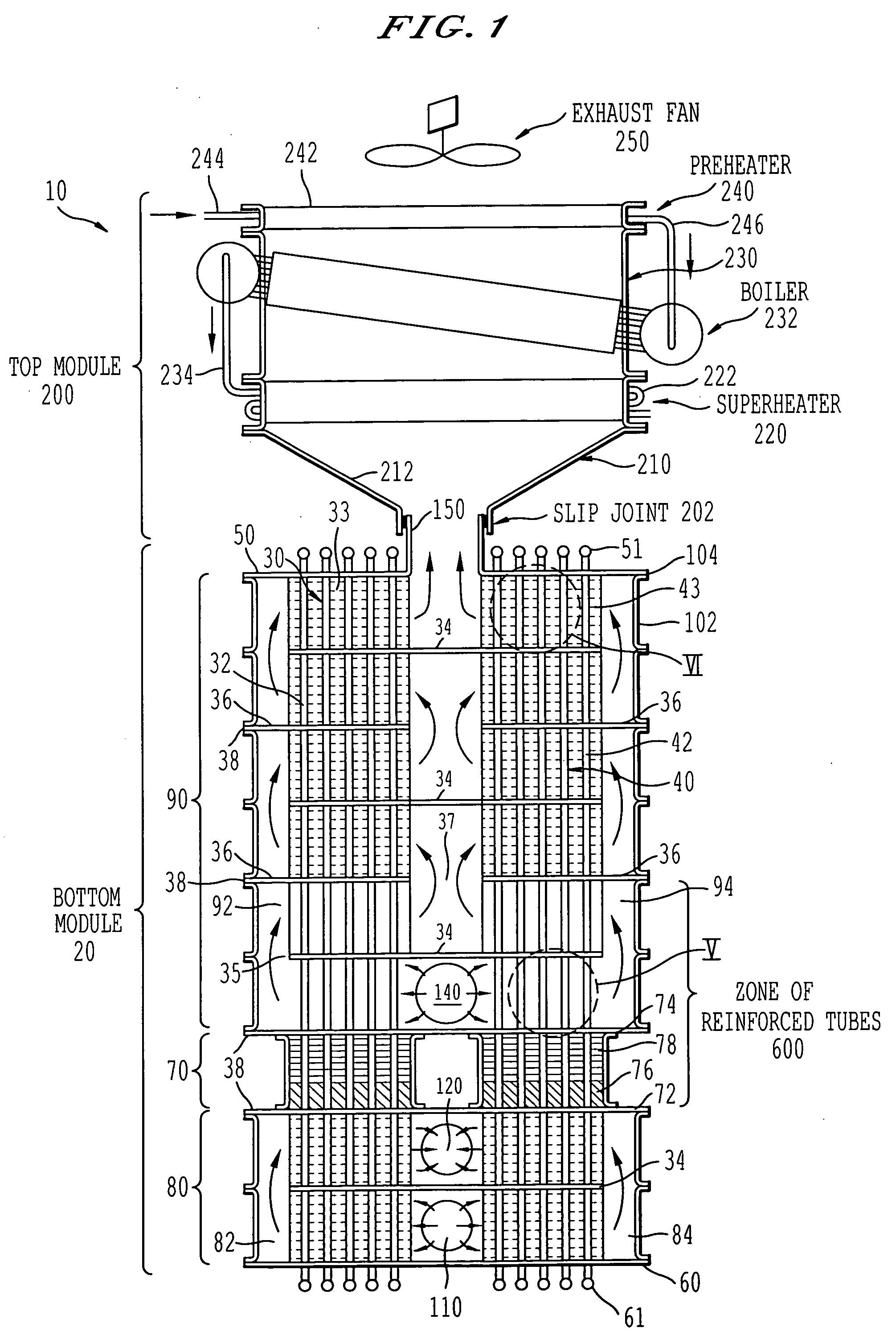
[0024]FIG. 1 shows a heat exchanger 10 including a bottom module 20 having a first tubular heat exchanger core 30 and a second tubular heat exchanger core 40. The first core 30 includes an array of substantially-parallel conduits or tubes 32, which are sealingly connected between a first tubesheet 50 and a second tubesheet 60. The second core 40 includes an array of substantially-parallel conduits or tubes 42, which are sealingly connected between the first tubesheet 50 and the second tubesheet 60. A first fluid flows from one of a plurality of inlet manifolds 51 provided adjacent to the first tubesheet 50, through tubes of the array of tubes 32 and the ...


PUM

PropertyMeasurementUnit
temperatureaaaaaaaaaa

Abstract

A heat exchange apparatus including a housing, a first array of fluid conduits provided within the housing, and a second array of fluid conduits provided within the housing. The first and second arrays of fluid conduits are configured to carry a first fluid. The heat exchange apparatus also includes a first fluid passageway provided within the housing, where the first fluid passageway is defined by an internal surface of the housing and by a baffle plate. The first fluid passageway is configured to carry a second fluid. The baffle plate is configured to divide the first fluid passageway into a first flow path and a second flow path, where the first array of fluid conduits extends through the first flow path and the second array of fluid conduits extends through the second flow path.

Description

BACKGROUND OF THE INVENTION [0001] 1. Field of the Invention [0002] The present invention relates generally to heat exchangers and methods of constructing heat exchangers. [0003] 2. Discussion of the Background [0004] Heat exchangers and heat exchange chemical reactors having large arrays of parallel tubes are known in the art. Traditional design practices for such articles are codified in design standards. U.S. Pat. No. 6,497,856 (the '856 patent), which is hereby incorporated by reference, teaches a heat exchange chemical reactor for producing hydrogen from natural gas, propane, liquefied petroleum gas (LPG), alcohols, naphtha and other hydrocarbon fuels. Typical industrial applications include feedstock for ammonia synthesis and other chemical processes, in the metals processing industry, for semiconductor manufacture and in other industrial applications, petroleum desulfurization, and hydrogen production for the merchant gas market. The demand for low-cost hydrogen at a smaller ...

Claims


Application Information

Patent Timeline
Patent Type & Authority Applications(United States)
IPC IPC(8): C01B3/24F28D7/00F28F9/22F28F19/06
CPCF28D7/0075F28D7/0091F28F2225/04F28F9/22F28F19/06F28D7/1607Y02P20/129F28D7/16F28D7/08
Inventor LOMAX, FRANKLIN D. JR.LETTOW, JOHN S.JAMES, BRIAN D.
Owner LAIR LIQUIDE SA POUR LETUDE & LEXPLOITATION DES PROCEDES GEORGES CLAUDE
Why Eureka
Try Eureka