
Production method for ceramic porous material

a production method and porous material technology, applied in the field of ceramic porous materials, can solve the problems of low mechanical strength, poor transmissivity, and generation of dust (particles), and achieve the effects of high porosity, excellent transmissivity, and high strength

Inactive Publication Date: 2005-09-15
COVALENT MATERIALS CORP
View PDF2 Cites 4 Cited by
  • Summary
  • Abstract
  • Description
  • Claims
  • Application Information

AI Technical Summary

Benefits of technology

[0013] Accordingly, an object of the present invention is to provide a production method for a ceramic porous material having a high strength for its high porosity and the excellent transmissivity without the risk of generation of dusts.
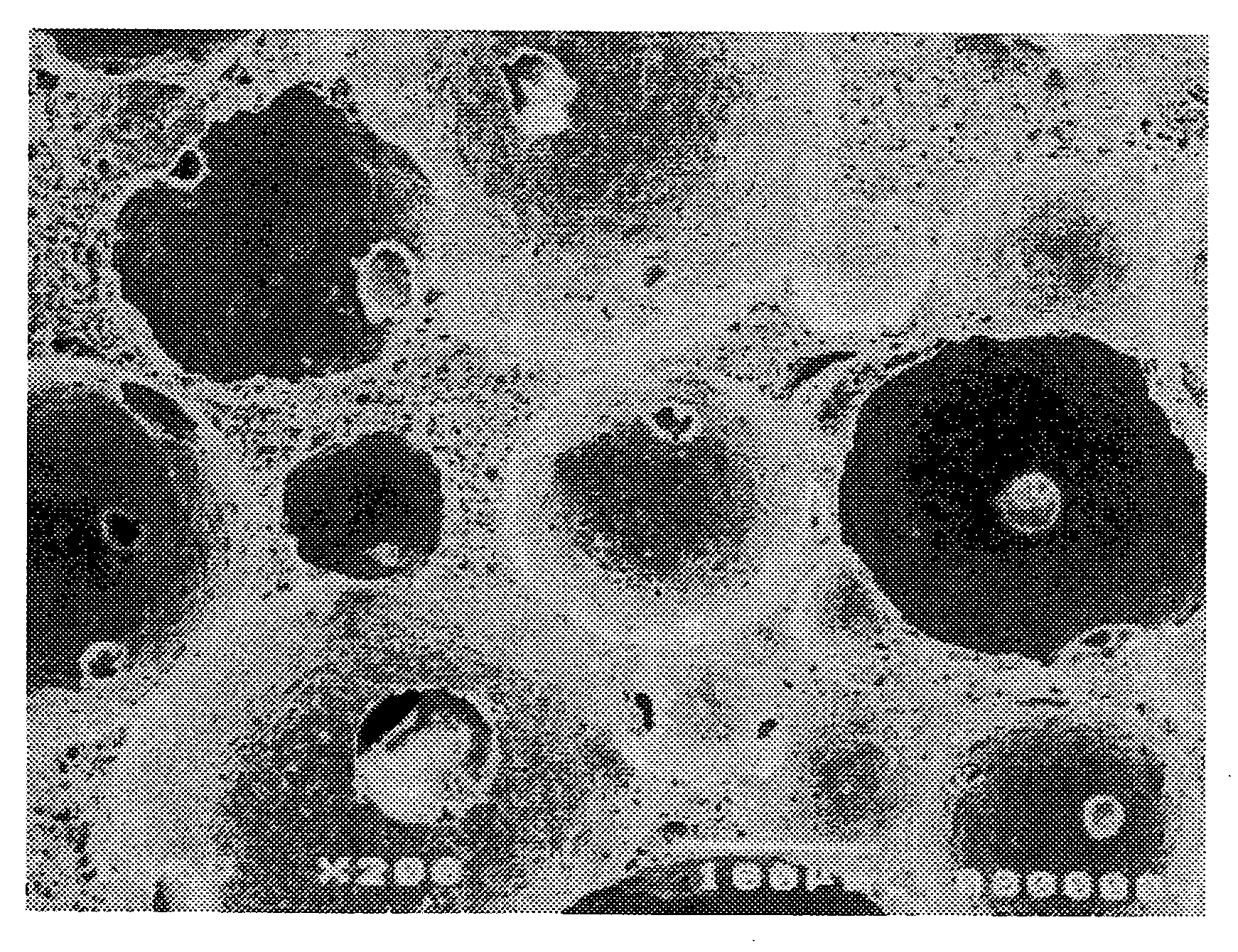
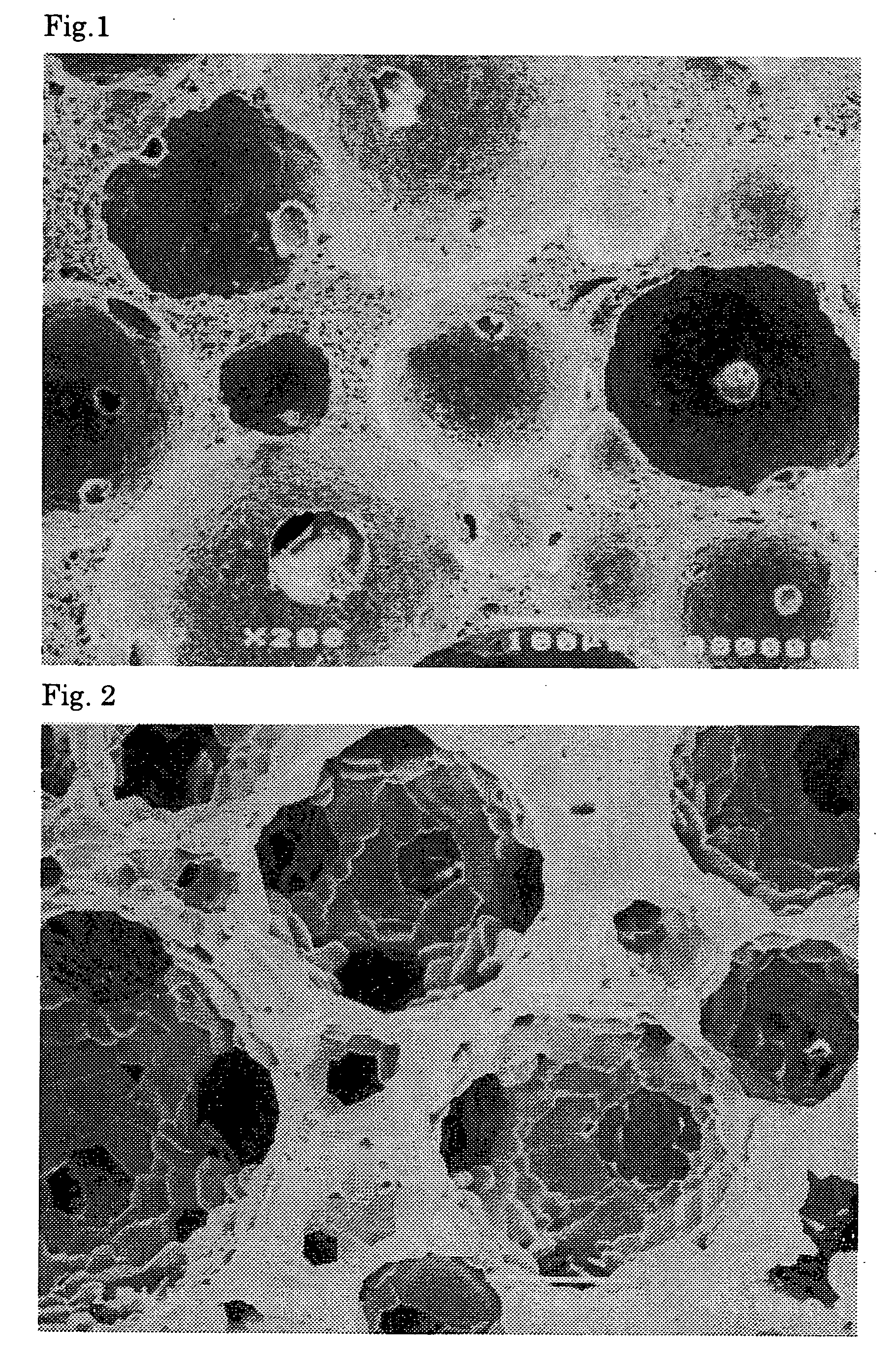
[0020] In contrast, according to the first aspect of the production method for a ceramic porous material, the abnormal part at the rim of each communication hole can be eliminated so that the hole size of the communication holes is made larger. The mechanical elimination of the rim of each communication hole can be executed by permeating a liquid such as water or a gel such as an agar with a hard fine particle such as a diamond powder and a silicon carbide powder dispersed through the compact, the temporarily baked product, or the sintered or fired product. Although the elimination of the rim of each communication hole can be executed also to the sintered or fired product, it is more efficient to execute the same to the temporarily baked product with a low strength, and in the case of executing the same to the compact, a liquid medium not to dissolve the compact is used.
[0023] According to the second aspect of the production method for a ceramic porous material, similar to the case of the first aspect, the abnormal part at the rim of each communication hole can be eliminated so that the hole size of the communication holes is made larger.
[0025] This is because the abnormal part unstable in terms of shape has a larger dissolution speed than that of the other parts. It is also possible to promote the dissolution speed by heating and pressuring the phosphoric acid (pressuring the phosphoric acid is dangerous) or the sulfuric acid at the time of the soaking operation.

Problems solved by technology

However, according to the conventional ceramic porous material, problems are involved in that the mechanical strength is low, dusts (particles) are generated, and the transmissivity is poor.

Method used


Image

  • Production method for ceramic porous material
  • Production method for ceramic porous material

Examples


examples 6 to 10

[0046] First, with reference to the examples 1 to 5, 5 compact pieces were produced with different porosities in the substantially same manner therewith. The compacts were temporarily baked so as to obtain columnar-shaped compacts. After the elimination process by permeation with the silicon carbide slurry, they were made to have the same porosity.

[0047] Next, in the same manner as in the examples 1 to 5, the temporarily baked products were fired for providing the fired products so as to obtain 5 pieces of alumina ceramic porous materials of a 60% porosity.

[0048] The porosity of the obtained alumina ceramic porous materials, the existence or absence of the abnormal part, the pressure loss and the time to the particle number zero count were measured in the same manner as in the examples 1 to 5. Results are shown in the table 2 together with those of the comparative example 1.

TABLE 2time to theparticleexistence ornumberabsence ofcondensationpressurezeroporositythe abnormalstrength...

example 16

[0061] First, the alumina ceramic porous material of the comparative example 1 was processed into a rectangular parallelepiped-like shape of a 1 cm square and a 10 cm length. A slurry with a sodium borate powder dispersed by 30% in an acetone was poured thereon for introducing the sodium borate slurry into the cells of the alumina ceramic porous material.

[0062] Next, after dying the acetone, it was introduced into a furnace kept at 1,000° C. for fusing the sodium borate. After maintaining the same in the furnace for 10 minutes, it was taken out from the furnace and cooled down in the air. Then, it was boiled in a diluted hydrochloric acid for 2 hours for dissolving and eliminating the sodium borate so as to obtain an alumina ceramic porous material.

[0063] The porosity, the existence or absence of the abnormal part, the condensation strength, the pressure loss and the time to the particle number zero count were measured as in the examples 1 to 5. Results are shown in the table 4 to...

examples 17 , 18

EXAMPLES 17, 18

[0065] The temporarily baked product of the comparative example 1 and the fired product of the comparative example 1 were fired or re-fired at 1,900° C. in a hydrogen gas atmosphere for 5 hours for providing a baked product or a re-baked product so as to obtain an alumina ceramic porous material, respectively. The crystal particles of both of the obtained ceramic porous materials had grain growth to about 20 μm. Moreover, the porosity, the existence or absence of the abnormal part, the condensation strength, the pressure loss and the time to the particle number zero count were measured as in the examples 1 to 5. Results are shown in the table 5 together with those of the comparative example 1.

TABLE 5time to theparticleexistence ornumberabsence ofcondensationpressurezeroporositythe abnormalstrengthlosscount(%)part(MPa)(KPa)(minute)example 1760Absent4000.10.1example 1860Absent4000.10.1Comparative60Exist300160example 1

[0066] As it is shown in the table 5, by denaturing...


PUM

PropertyMeasurementUnit
porosityaaaaaaaaaa
porosityaaaaaaaaaa
temperatureaaaaaaaaaa

Abstract

To provide a method for producing a ceramic porous material which has a high strength, though it has a high porosity, and which is excellent in permeability without dust generation. In a ceramic porous material having a three-dimensional mesh-like skeleton structure with a large number of substantially spherical adjacent cells communicating with each other via communication holes, the crystal particle size at the rim of each communication hole in the skeleton structure is provided substantially equal to the crystal particle size in the other parts.

Description

BACKGROUND OF THE INVENTION [0001] 1. Field of the Invention [0002] The present invention relates to a ceramic porous material having a bubble-like appearance to be used as a filter, a bubbler, a gas supplying member, a semiconductor producing device member, an artificial bone, a cell culturing supporter, an artificial organ, a catalyst supporter, or the like, and a production method therefor. [0003] 2. Description of the Related Art [0004] Conventionally, as a ceramic porous material of this kind, one having a three-dimensional mesh-like skeleton structure with a large number of substantially spherical adjacent cells (pores) communicating with each other via communication holes has been known (see the official gazette of the Japanese Patent Laid Open Application (JP-A) No. 4-202071 (U.S. Pat. No. 2,506,502). [0005] The ceramic porous material is produced by preparing a slurry by dispersing or dissolving in a solvent a ceramic powder and an organic substance to be hardened by the cr...

Claims


Application Information

Patent Timeline
Patent Type & Authority Applications(United States)
IPC IPC(8): C04B38/10
CPCC04B38/10C04B35/00C04B38/0045C04B38/0058
Inventor UEMOTO, HIDEOKAWAI, KAZUHIDESHIMAI, SHUNZOMATSUYAMA, TAKASHI
Owner COVALENT MATERIALS CORP
Learn More