

Systems and methods for laser texturing of surfaces of a substrate
a technology of laser texturing and substrate, applied in the direction of manufacturing tools, prosthesis, welding/soldering/cutting articles, etc., can solve the problems of scar tissue proximate to the implanted device, difficult if not impossible control of the orientation of the texturing formed on the substrate, significant alteration of the surface/near-surface chemistry,
- Summary
- Abstract
- Description
- Claims
- Application Information
AI Technical Summary
Benefits of technology
Problems solved by technology
Method used
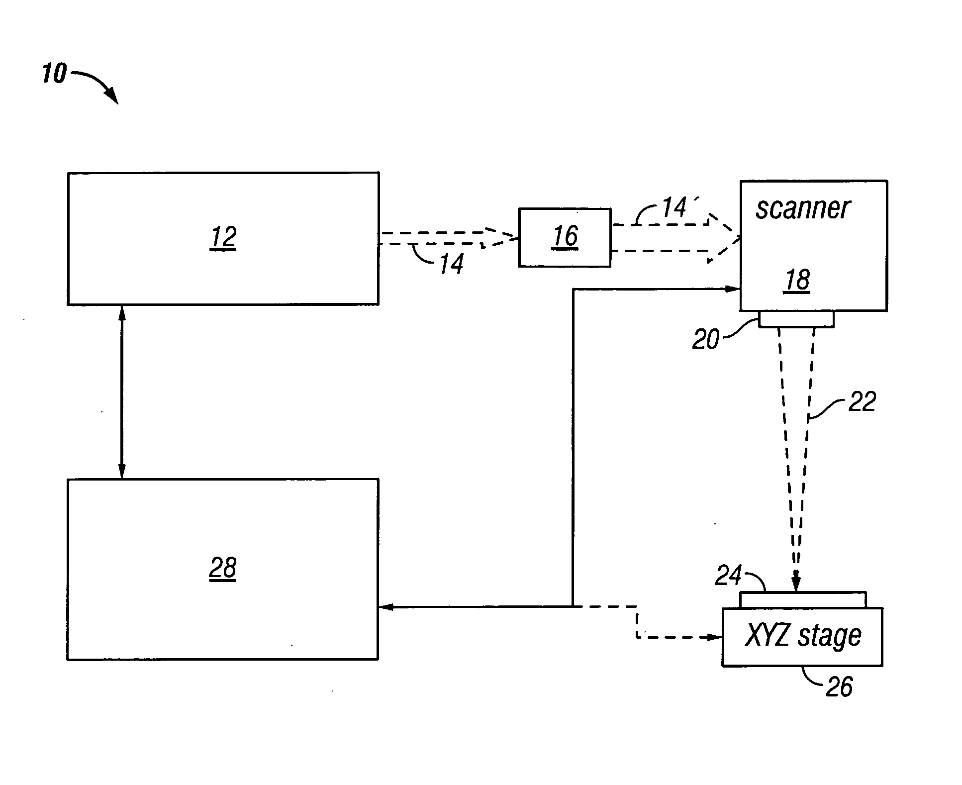
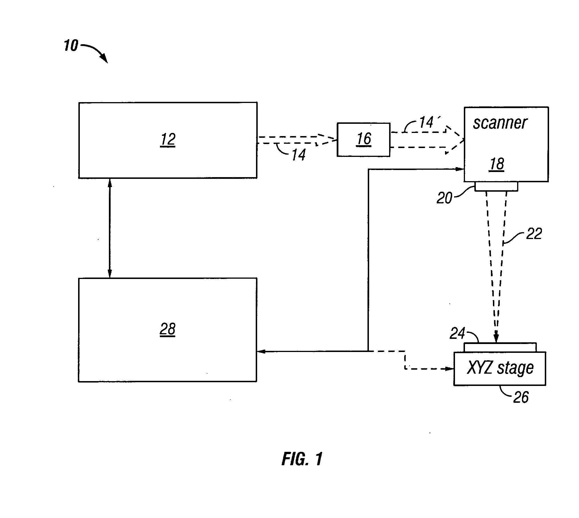
Image

Examples
example 1
[0062] A Q-switched, diode pumped solid-state (DPSS) UV laser was used to fabricate micro-groove geometries on a titanium alloy surface. The DPSS laser was utilized to introduce micro-groove geometries, with a variety of cells such as sarcoma and osteoblasts, with depths between approximately about 6 μm and about 150 μm in Ti and Ti-6Al-4V alloys. Further, micro-groove geometries having depths of approximately about 8 μm and about 16 μm may be produced by the appropriate control of pulse frequency, repetition rate and the number of scans.
example 2
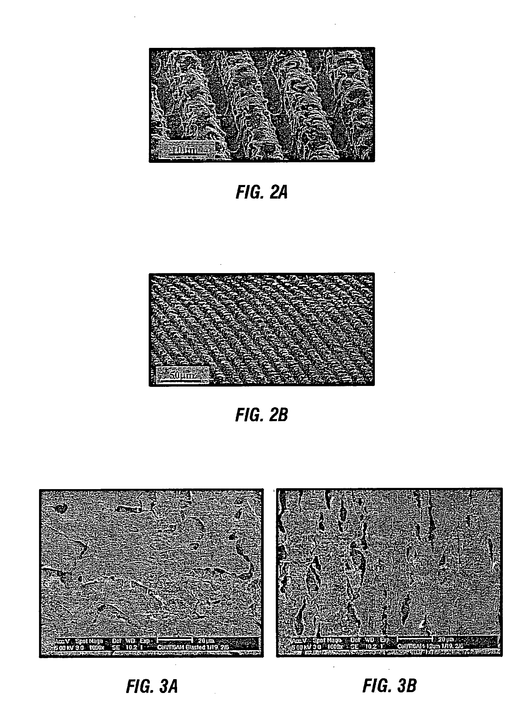
[0063] Groove dimensions and geometries were studied in relation to laser processing parameters. By way of illustration, and without limitation, nano-second UV laser processing parameters were investigated relative to the geometry and microstructure of a mill annealed Ti-6Al-4V alloy. The laser processing parameters, including but not limited to pulse repetition rate, feed speed, wavelength, and the like, were varied in order to produce micro-grooves with depths of approximately 12 μm. In one embodiment, optimal micro-groove geometries were shown to promote the contact guidance that can give rise to reduced scar tissue formation and improved osseo-integration.
[0064] Contact guidance of human osteosarcoma (HOS) cells on laser micro-grooved Ti6Al4V surfaces was achieved using the methods disclosed herein. As a result and accompanied by the lack of micro-structural defects, such as heat affected zones and micro-cracks, the devices modified using the systems and methods provided for he...
example 3
Cell Surface Interactions
[0066] HOS cells were used in a 2-day cell culture experiment on laser micro-grooved Ti6Al4V surfaces to investigate the cell-surface interactions between HOS cells and laser micro-grooved Ti6Al4V surfaces.
Cell Culture
[0067] HOS cells were maintained at 37° C. in humid 5% CO2-95% air. The culture medium was 89% DEEM, 10% fetal bovine serum, and 1% penicillin / streptomycin. Thereafter, the cells were split 1:5 whenever confluence was reached. The cells were harvested using trysin at 0.25% concentration. The cells were then centrifuged down to a pellet at 3500 revolutions per minute and resuspended in 1 mL of medium.
Ti6Al4V Surfaces
[0068] Micro-grooves were produced on the surfaces of two Ti-6Al-4V samples having approximate dimensions ¼″ X ¼″ X ½″, using a Spectra Physics Navigator II YHP40 laser having a laser output of 355 nm (UV). The samples were cut from a ¼″ thick bend bar specimen and mechanically polished utilizing colloidal silica for the final p...
PUM
| Property | Measurement | Unit |
|---|---|---|
| Time | aaaaa | aaaaa |
| Time | aaaaa | aaaaa |
| Time | aaaaa | aaaaa |
Abstract
Description
Claims
Application Information