Dielectric, gas treatment apparatus using the same, and plasma generator

a gas treatment apparatus and plasma generator technology, applied in plasma techniques, separation processes, energy-based chemical/physical/physico-chemical processes, etc., can solve the problems of increasing increasing the operational cost, increasing the treatment efficiency, etc., and achieving the effect of reducing the heat generation of the dielectric, reducing the size of the apparatus, and efficient trapping the treatment target substan

Inactive Publication Date: 2005-09-29
CANON KK
View PDF3 Cites 40 Cited by
  • Summary
  • Abstract
  • Description
  • Claims
  • Application Information

AI Technical Summary

Benefits of technology

[0012] In the dielectric having such a constitution, a treatment target substance flows through the passage in which plasma is generated for oxidation thereof, to thereby allow detoxification of the treatment target substance. Oxidation of the treatment target substance is accelerated by means of the catalyst, and treatment efficiency is further enhanced. The treatment target substance is efficiently trapped within the passage by means of the adsorbent. Thus, the treatment target substance is more assuredly oxidized, and an untreated part is hardly discharged out of a system. In addition, the dielectric having a structure including the dielectric substrate covered with the ferroelectric film of a larger dielectric constant than that of the dielectric member allows plasma production from a ferroelectric film at a low voltage. Further, heat generation of the dielectric can be suppressed, to thereby suppress adverse effects on plasma production characteristics and maintain stable plasma.
[0021] Further, the plasma generator of the present invention can realize plasma production at a large ratio of a plasma space volume to a plasma reactor volume, and further plasma production with high electric power efficiency.

Problems solved by technology

The VOC detoxification technique employs a photodecomposition method, a catalyst decomposition method, a power burner combustion method, and the like, but those techniques have problems such as increase in apparatus size, increase in operational cost, generation of toxic substances, and treatment efficiency.
However, when the dielectric pellets are filled between the electrodes, a void ratio is considerably reduced, causing a large pressure loss while a gas flows through a plasma space.
Thus, the technique has problems of increase in apparatus cost or operational cost.
Further, electrical characteristics of the dielectric are generally affected by temperature.
Thus, it is pointed out that increase in applied voltage causes problems of heat generation of the dielectric, adverse effects on a plasma state, and reduction in treatment efficiency.
In order to solve the problems, it is effective to increase a gas flow rate and thus enhance an air cooling effect, which may disadvantageously cause increase in fan capacity or increase in fan power due to increased pressure loss.

Method used


Image

  • Dielectric, gas treatment apparatus using the same, and plasma generator
  • Dielectric, gas treatment apparatus using the same, and plasma generator
  • Dielectric, gas treatment apparatus using the same, and plasma generator

Examples


example 1

(Example 1)

[0070]FIG. 10 is a schematic diagram showing a constitution of a gas treatment apparatus used in Example 1 and Comparative Examples 1 and 2. A cylinder 114 of a gas to be treated filled with the gas to be treated is connected to a gas introduction port of a gas treatment apparatus 101 through a flow controller 115. A plasma treatment chamber has a chamber volume of 16 cm3. A gas discharge port is connected to an analytical instrument 116 (gas detector tube, manufactured by Gastec Corporation) through a pipe. The gas to be treated is an ammonia gas of 10 ppm, and a flow rate thereof is 16 l / min.

[0071] A constitution of electrodes / dielectric of Example 1 is somewhat simplified compared to those described in the above embodiments, and includes: a high-voltage electrode 105 (tungsten bar of 1 mmφ) connected to a high-voltage power supply 112; ground electrodes 104a and 104b (stainless steel mesh) on both sides of the high-voltage electrode 105; and dielectrics 106a and 106b ...

example 2

(Example 2)

[0075] In Example 2, detoxification treatment of a gas containing a volatile substance was conducted using a gas treatment apparatus having a different constitution as follows.

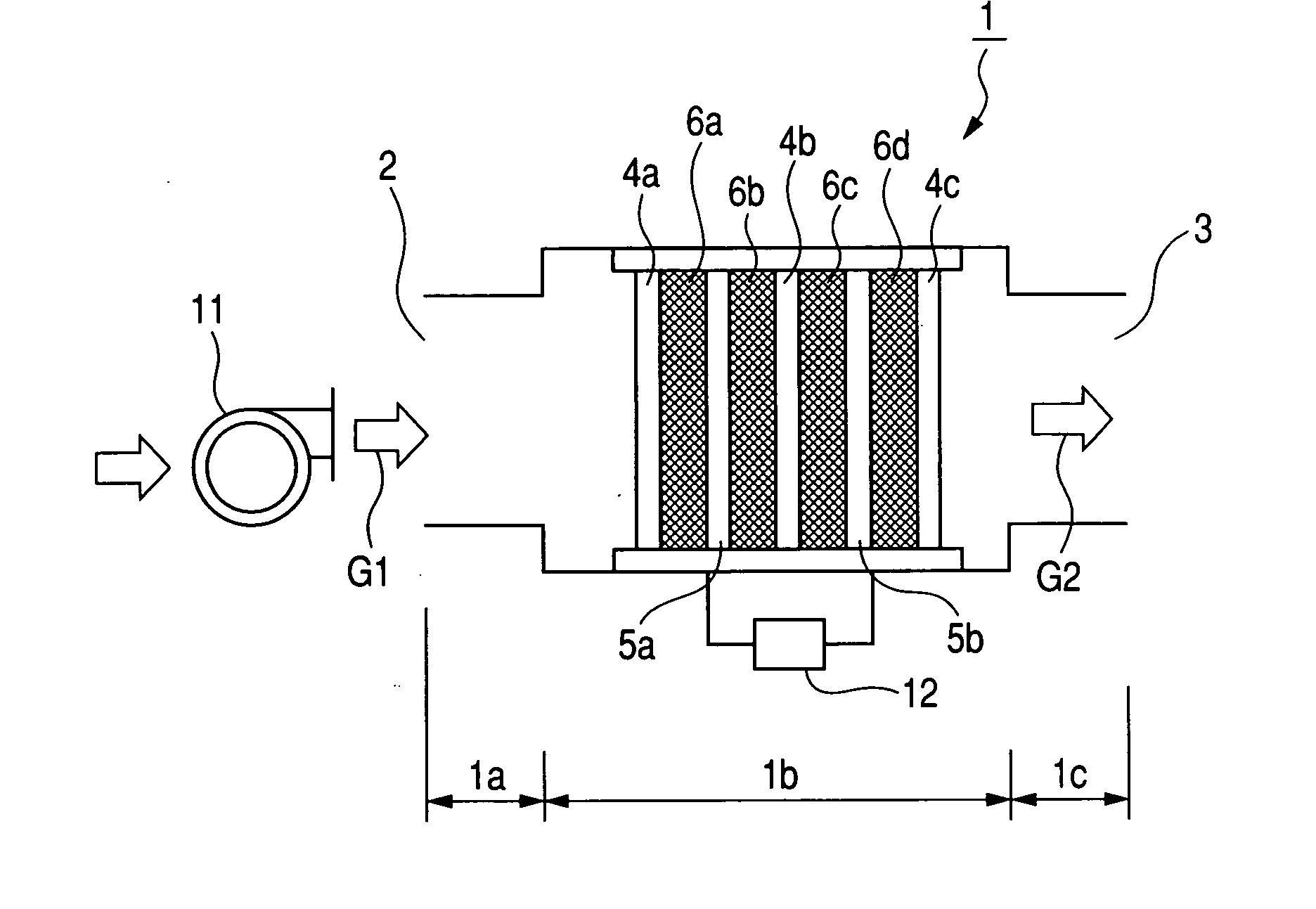
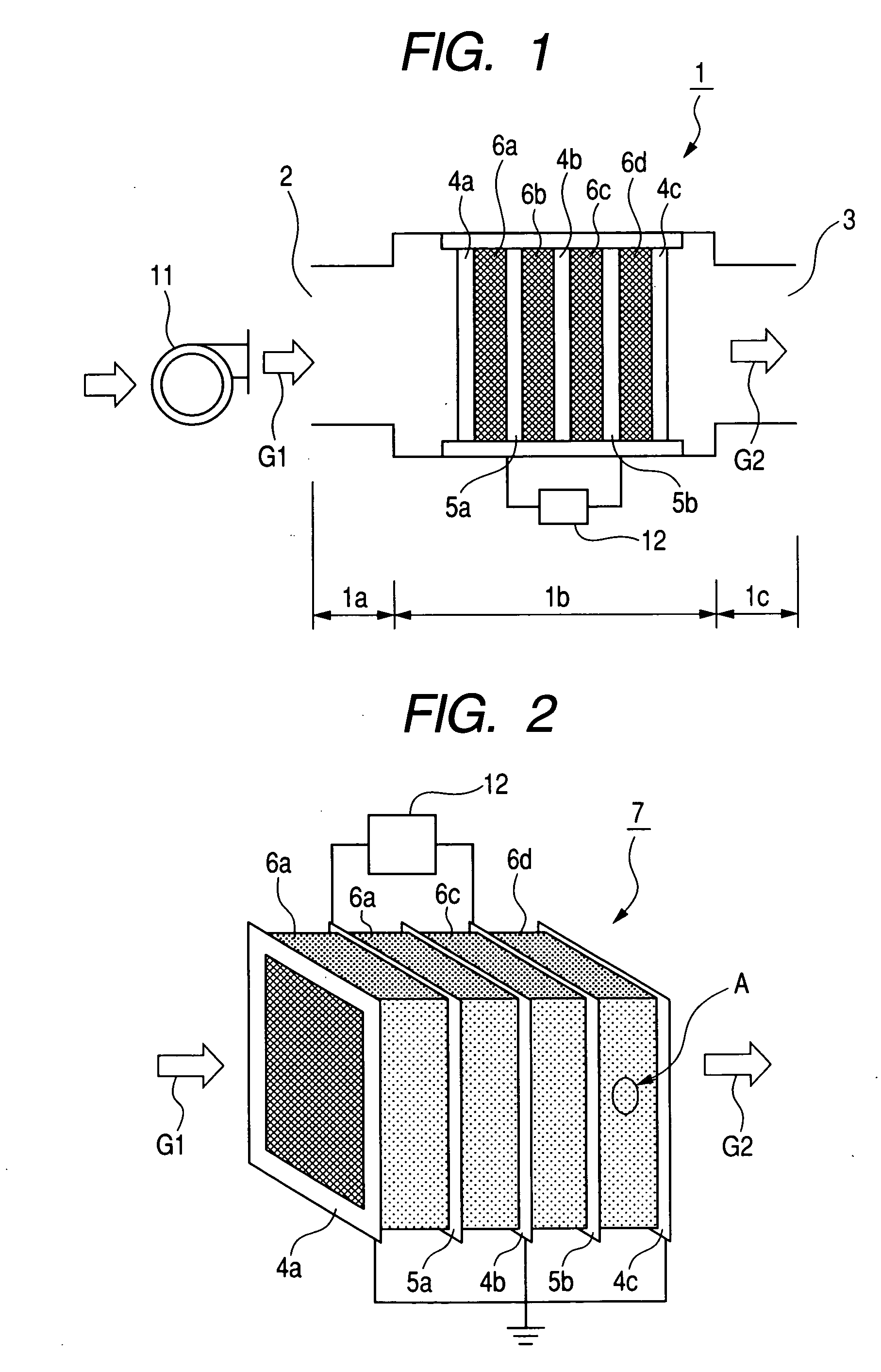
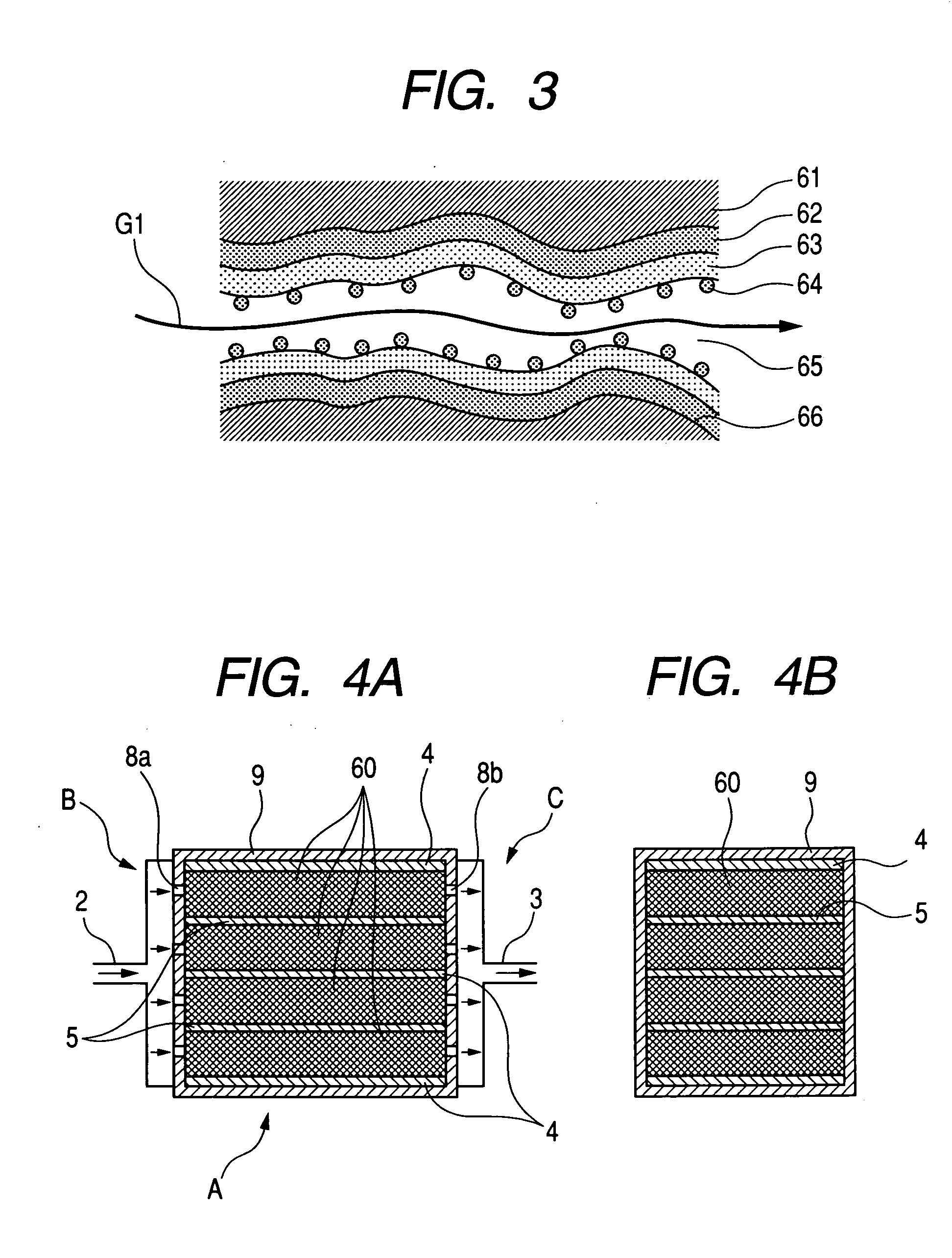
[0076]FIG. 12 is a schematic diagram showing a constitution of a gas treatment apparatus employing a plasma generator used in Example 2. The gas treatment apparatus employed a plasma generator having a parallel plate plasma reactor of the same constitution as that shown in FIGS. 4A and 4B. A gas introduction pipe 13 connected to a gas introduction port 1 of the plasma generator extended from a gas cylinder 14 of a gas to be treated, and was provided with a gas flow controller 15. An analytical instrument 16 was connected to a gas discharge pipe 14 connected to a gas discharge port 3. A high-voltage power supply 12 was connected between a ground electrode 4 and a high-voltage electrode 5 of the plasma generator. A dielectric member 60 used was prepared by: applying barium titanate (dielectric consta...


PUM

PropertyMeasurementUnit
frequencyaaaaaaaaaa
frequencyaaaaaaaaaa
porosityaaaaaaaaaa

Abstract

A plasma generator for producing plasma under normal pressure by applying a voltage between a ground electrode and a high-voltage electrode, the plasma generator including the ground electrode, the high-voltage electrode, and a dielectric member arranged between the ground electrode and the high-voltage electrode, in which the dielectric member has a structure including a porous ceramic substrate covered with an inorganic dielectric substance.

Description

BACKGROUND OF THE INVENTION [0001] 1. Field of the Invention [0002] The present invention relates to a dielectric used in a gas treatment apparatus for detoxifying a gas containing volatile organic compounds (hereinafter, referred to as VOC) discharged from various industrial processes through a non-thermal plasma decomposition method, to a gas treatment apparatus using the same, and to a plasma generator. [0003] 2. Related Background Art [0004] VOC are toxic chemical substances such as toluene, xylene, and methyl ethyl ketone (MEK) generated during a coating process or the like employing an organic solvent. In actuality, VOC had been emitted into atmosphere. However, reduction of VOC which are substances applying environmental load has been demanded socially, reflected by a recent enforcement of Pollutant Release and Transfer Register (PRTR), for example. Thus, a VOC detoxification technique has been studied extensively. The VOC detoxification technique employs a photodecomposition...

Claims


Application Information

Patent Timeline
Patent Type & Authority Applications(United States)
IPC IPC(8): B01D53/32B01J19/08B01J19/24H05H1/24
CPCB01D53/32B01J19/088B01J19/2485B01J19/249B01J2219/0813B01J2219/0835H05H1/24B01J2219/0875B01J2219/0892B01J2219/0894B01J2219/182B01J2219/1923B01J2219/2459B01J2219/0847H05H1/2465H05H1/2441
Inventor KANEKO, YOSHIAKINISHIGUCHI, TOSHIJI
Owner CANON KK
Why Eureka
Try Eureka