

Gas diffusion layer and fuel cell using the same
- Summary
- Abstract
- Description
- Claims
- Application Information
AI Technical Summary
Benefits of technology
Problems solved by technology
Method used
Image

Examples
example 1
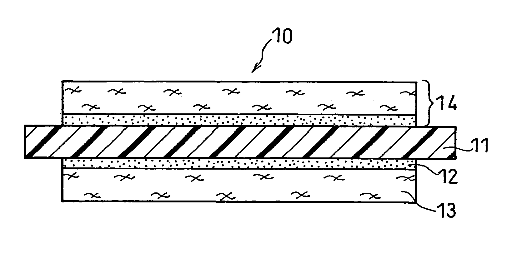
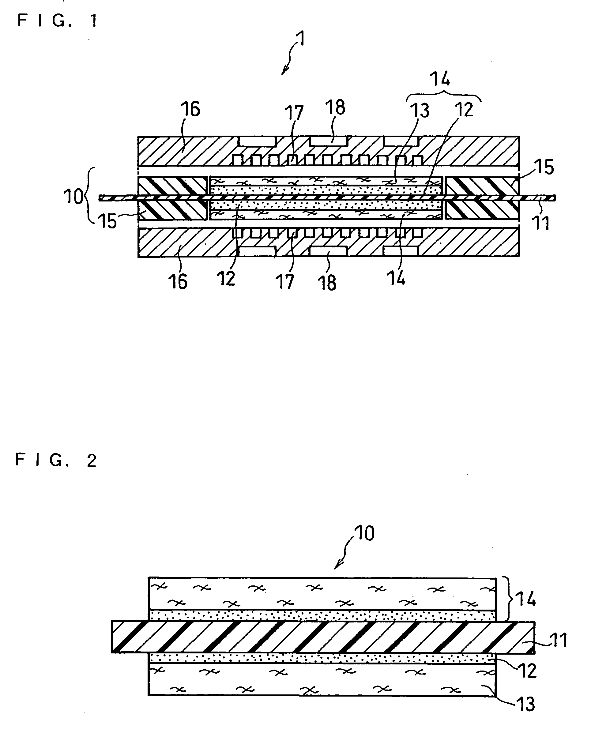
[0103] In this example, a membrane-electrode assembly (MEA) having the structure shown in FIG. 2 was first fabricated. Then, a unit cell (polymer electrolyte fuel cell) having the structure shown in FIG. 1 was constructed.
[0104] Carbon cloth (GF-20-31E available from Nippon Carbon Co., Ltd.) plainly woven with carbon fibers serving as the porous conductive substrate was immersed in a dispersion of tetrafluoroethylene-hexafluoropropylene copolymer (FEP) (ND-1 available from Daikin Industries, Ltd.). for water repellent treatment. The porous conductive substrate treated for water repellency was dried at 100° C., and then baked at 350° C.
[0105] Subsequently, carbon black was added and dispersed in water containing a surfactant (Triton X available from Kanto Kagaku) using a planetary mixer (T. K. HIVIS MIX available from Tokushu Kika Kogyo Co., Ltd.) under a reduced pressure for 5 hours. A polytetrafluoroethylene (PTFE) resin dispersion (D-1 available from Daikin Industries, Ltd.) was...
example 2
[0112] In this example also, a membrane-electrode assembly (MEA) having the structure shown in FIG. 2 was first fabricated. Then, a unit cell (polymer electrolyte fuel cell) having the structure shown in FIG. 1 was constructed.
[0113] Carbon cloth similar to the one used in EXAMPLE 1 as the porous conductive substrate was subjected to pressing treatment. One surface of the carbon cloth was then lightly rubbed with an industrial brush so as to make the surface fuzzy. The carbon cloth was immersed in a FEP resin dispersion for water repellency. The carbon cloth treated for water repellency was then dried at 100° C. and further baked at 350° C. with the fuzzy surface (second surface) facing upward.
[0114] Subsequently, the surfactant, water and carbon black were dispersed using the planetary mixer under a reduced pressure for 3 hours. A PTFE resin dispersion was added thereto, which was further kneaded for 30 minutes to yield an ink for forming the water repellent conductive layer.
[01...
example 3
[0119] In this example also, a membrane-electrode assembly (MEA) having the structure shown in FIG. 2 was first fabricated. Then, a unit cell (polymer electrolyte fuel cell) having the structure shown in FIG. 1 was constructed.
[0120] Carbon paper (GDL30AA available from SGL Carbon Japan Co., Ltd) serving as the porous conductive substrate was immersed in the PTFE resin dispersion used in the EXAMPLE 1 for water repellent treatment, followed by drying at 100° C. Then, a water repellent conductive layer was formed on one surface of the porous conductive substrate treated for water repellency by the application of the ink in the same manner as in EXAMPLE 1, which was dried at 80° C. and baked at 300° C. Thereby, a gas diffusion layer of the present invention whose smooth first surface was composed of the water repellent conductive layer was formed.
[0121] The particles contained in the ink had an average particle size of 3 μm with a maximum particle size of 30 μm.
[0122] Similar to EX...
PUM
 Abstract
Description
Claims
Application Information