Analog transmitter using an external cavity laser (ECL)

an external cavity laser and analog transmitter technology, applied in the field of optical communication, can solve the problems of limiting the maximum amount of optical power that can be launched into the fiber, limiting the transmission distance, and limiting the transmission reach, so as to reduce the cost, improve the level of sbs suppression, and eliminate electronic dithering

Inactive Publication Date: 2005-10-06
EMCORE INC +1
View PDF32 Cites 61 Cited by
  • Summary
  • Abstract
  • Description
  • Claims
  • Application Information

AI Technical Summary

Benefits of technology

[0010] The present invention relates to an analog transmitter that eliminates or significantly reduces the requirement for predistortion circuitry commonly used in the prior art to correct for second or third order distortion. Furthermore, some embodiments of the analog transmitters described herein reduce costs through the use of direct-modulated external cavity lasers and / or provide application-specific chirp levels. In addition, the analog transmitter described herein improves the level of SBS suppression leading to the elimination of electronic dithering or a reduction in the level of such dithering required. The advances described herein lead to reduced material and labor costs, enhanced link design performance, improved manufacturing margins, and relaxed requirements on the level of technical expertise that is required in system manufacturing.

Problems solved by technology

SBS can limit transmission reach (that is, transmission distance) and can also limit the maximum amount of optical power that can be launched into the fiber.
Externally modulated transmitters seem to offer the best performance for many optical communication systems but at the expense of high cost, high optical coupling losses (typically about 5 to about 7 decibels, dB) and generally require sophisticated techniques for linearization of the analog signal.

Method used


Image

  • Analog transmitter using an external cavity laser (ECL)
  • Analog transmitter using an external cavity laser (ECL)
  • Analog transmitter using an external cavity laser (ECL)

Examples


Embodiment Construction

[0031] After considering the following description, those skilled in the art will clearly realize that the teachings of the invention can be readily utilized for the design, fabrication and / or use of analog optical transmitters including components and subsystems thereof.

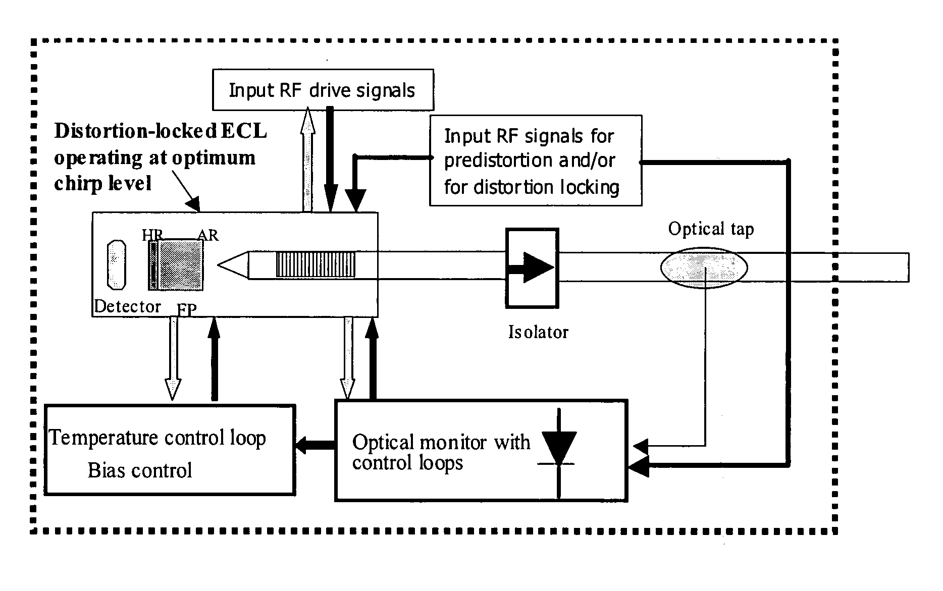
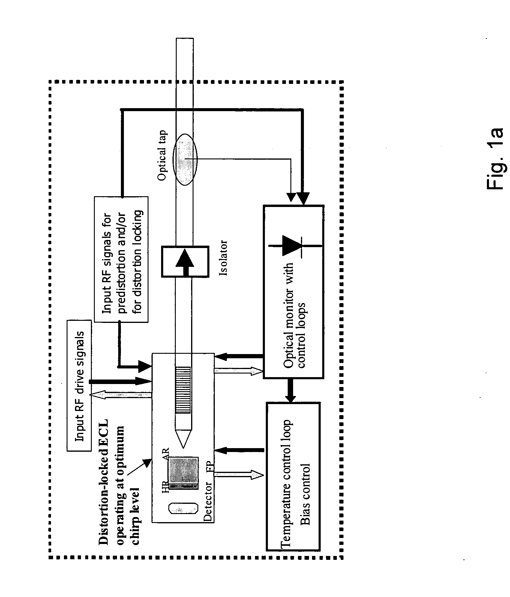
[0032] The present invention relates to optical analog transmitters incorporating external cavity lasers, ECLs, as well as uses in and for broadcast and narrowcast applications. Typical structures for ECLs are given in FIG. 2 including a laser diode 200 having one side coated with an anti-reflective (AR) film or coating 201. The face of the laser diode opposite the AR film is coated with a highly reflective (HR) film or coating 202, thereby providing one reflective end of the optical feedback cavity. In addition to laser diode 200, typical ECLs also include other optical elements chosen to work in combination with the laser diode. Such optical elements and their optical characteristics can conveniently be represent...


PUM


Abstract

The present invention relates to an analog transmitter using an external cavity laser (ECL) in which specific characteristics of the ECL are enhanced and exploited to improve 2nd and 3rd order distortion while increasing the threshold for the occurrence of deleterious stimulated Brillouin scattering (SBS). The performance of the ECL shows a substantial reduction in distortion occurring over certain narrow ranges of operating temperatures. Optical, electronic, thermal and/or mechanical methods are described that cause this “distortion dip” to be moved to, or created at, stable regions of ECL operation, away from mode hops. Methods are also described that allow the distortion dip to be moved to, or created at, ECL operating regions in which sufficiently high chirp occurs, thereby reducing SBS. Transmitters and other devices employing these and related techniques are also described.

Description

CROSS REFERENCE TO RELATED APPLICATIONS [0001] This application claims priority from provisional patent application Ser. No. 60 / 558,927 filed Apr. 2, 2004, and provisional patent application Ser. No. 60 / 562,762, filed Apr. 16, 2004, and provisional patent application Ser. No. 60 / 638,679 filed Dec. 23, 2004, pursuant to one or more of 35 U.S.C. § 119, § 120, § 365. The entire contents of all cited provisional patent applications are incorporated herein by reference for all purposes.BACKGROUND OF THE INVENTION [0002] 1. Field of Invention [0003] This invention relates generally to the field of optical communications and, more particularly, to an analog transmitter and external cavity laser suited for use in optical communication systems. [0004] 2. Description of the Prior Art [0005] Analog transmitters for both broadcast and narrowcast (QAM-format) applications in cable television (CATV) commonly use directly-modulated distributed feedback (DFB) lasers or externally modulated sources ...

Claims


Application Information

Patent Timeline
Patent Type & Authority Applications(United States)
IPC IPC(8): H01S3/04H01S5/00H01S5/02H01S5/022H01S5/024H01S5/028H01S5/042H01S5/0683H01S5/0687H01S5/14H01S5/40H04B10/04
CPCH01S3/1055H01S2301/03H01S5/0064H01S5/0078H01S5/02216H01S5/02248H01S5/02284H01S5/02415H01S5/02438H01S5/028H01S5/0427H01S5/06804H01S5/0683H01S5/0687H01S5/141H01S5/147H01S5/4012H01S5/4062H01S5/4087H01S3/1398H01S5/02325H01S5/02251
Inventor KUPERSHMIDT, VLADIMIRMAJOR, JOHNSIALA, SABEUR
Owner EMCORE INC
Why Eureka
Try Eureka