
Process for producing a high density by high velocity compacting

a high-speed compacting and high-temperature technology, applied in the direction of presses, forging hammers, shaping presses, etc., can solve the problems of high temperature increase, phase change in material, and the machine according to these documents does not work so well, so as to improve sequence control and reduce running costs

Inactive Publication Date: 2005-10-06
OLSSON KENT +1
View PDF3 Cites 8 Cited by
  • Summary
  • Abstract
  • Description
  • Claims
  • Application Information

AI Technical Summary

Benefits of technology

[0011] The object of the present invention is to achieve a low cost process for efficient production of products from a particulate material or a solid material by coalescence or compaction to a higher density. These products may be both medical devices such as medical implants or bone cement in orthopaedic surgery, instruments, such as surgical knives, or diagnostic equipment, or non medical devices such as ball bearings, cutting tools, sinks, baths, displays, glazing (especially aircraft), lenses and light covers. Another object is to achieve a product of the described type.
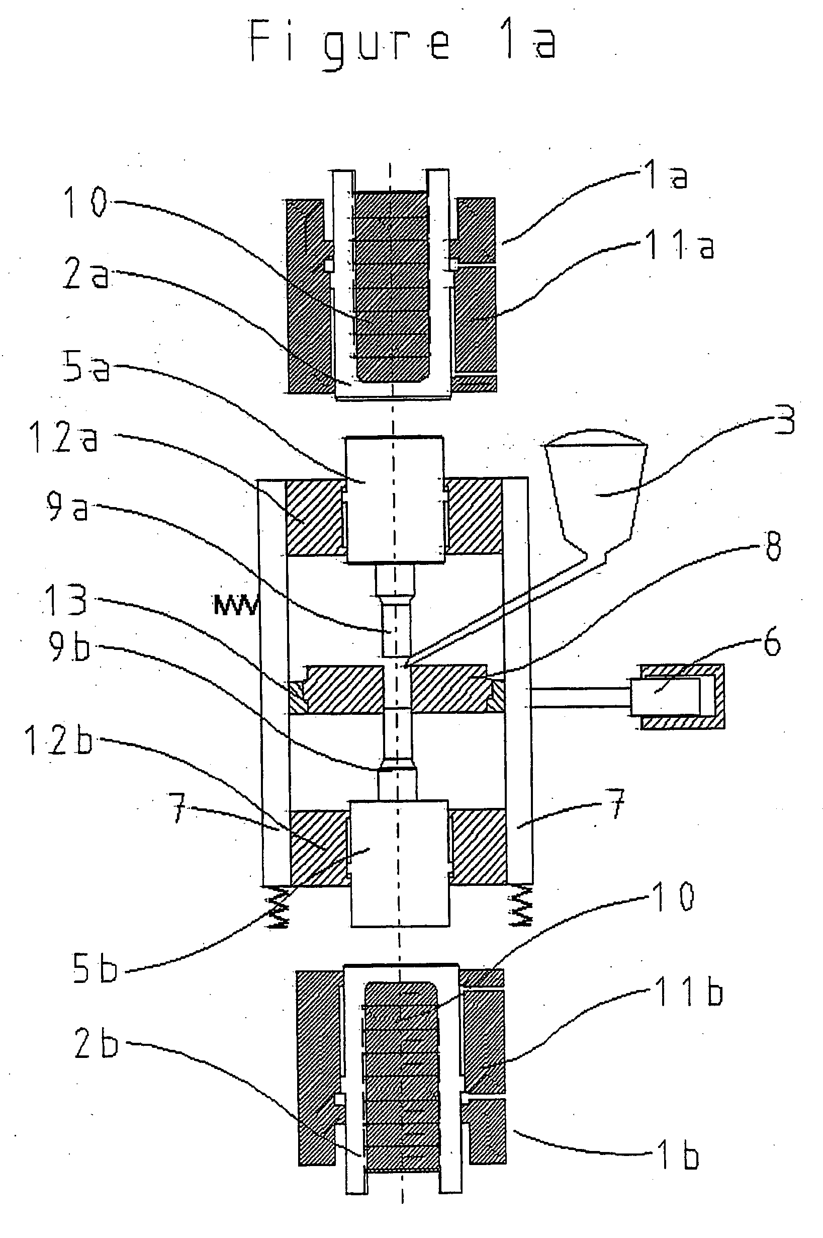
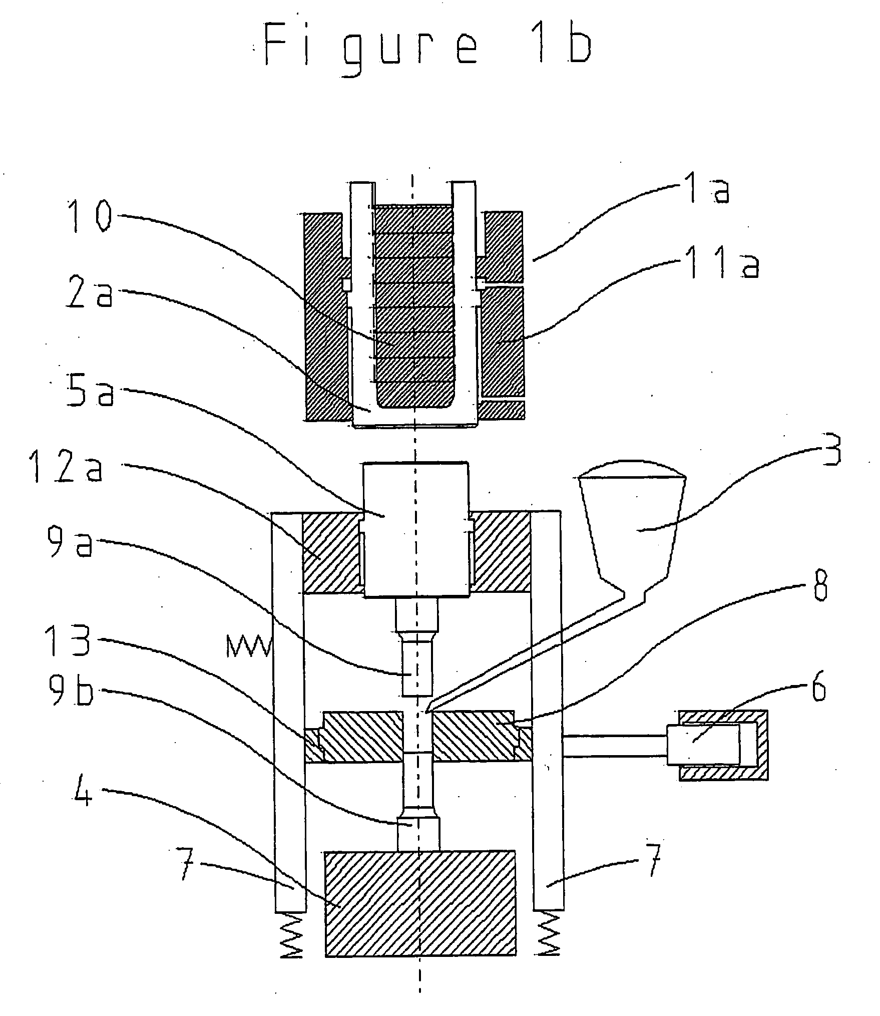
[0015] The method according to the invention may utilise hydraulics in the percussion machine, which may be constructed on the same principle as the machine utilised in WO-A1-9700751 and SE 9803956-3. When using pure hydraulic means in the machine, the striking unit or units can be given such movement as to, upon impact with the material to be compressed, emit sufficient energy at sufficient speed for coalescence to be achieved. This coalescence may be adiabatic. A stroke is carried out quickly and for some materials the wave in the material decay in between 5 and 15 milliseconds. The use of hydraulic may also give a better sequence control and lower running costs compared to the use of compressed air.

Problems solved by technology

The strokes according to the method described in WO-A1-9700751, give a locally very high temperature increase in the material, which can lead to phase changes in the material during the heating or cooling.
It has now been found that the machine according to these documents does not work so well.
For example, the time intervals between the strokes, which they mention, are not possible to attain.
Also, the rebounding strokes have proved to result in cracking of the material.

Method used


Image

  • Process for producing a high density by high velocity compacting
  • Process for producing a high density by high velocity compacting
  • Process for producing a high density by high velocity compacting

Examples


examples

1. Powder Height Study

[0117] Metal, ceramic and polymer powders were tested in a powder height study. The powder used were stainless steel, hydroxyapatite and UHMWPE. See table 2 for properties for the powders tested.

TABLE 2Technical data for the powders tested in the powder height study.PropertiesStainless steel 316LHydroxyapatiteUHMWPE1.Particle size(micron)2.Particle0.60 wt % > 150—distribution (micron)42.70 wt % 3.ParticleIrregularIrregularIrregularmorphology4.PowderWater atomisedWet chemistry—productionprecipitation5.Crystal structureFCCApatite50% amorphous6.Theoretical7.903.15 g / cm30.94density (g / cm3)7.Apparent density2.640.650(g / cm3)8.Melt temperature14271600125(° C.)9.Sintering1315900—temperature (° C.)10.Hardness160-190 HV450 HVR50-70 (Rockwell)

Metal

[0118]FIGS. 6 and 7 show relative density as a function of impact energy per mass and total impact energy, respectively, for samples processed with different powder masses. All samples were tested in the same cylindrical m...


PUM

PropertyMeasurementUnit
Temperatureaaaaaaaaaa

Abstract

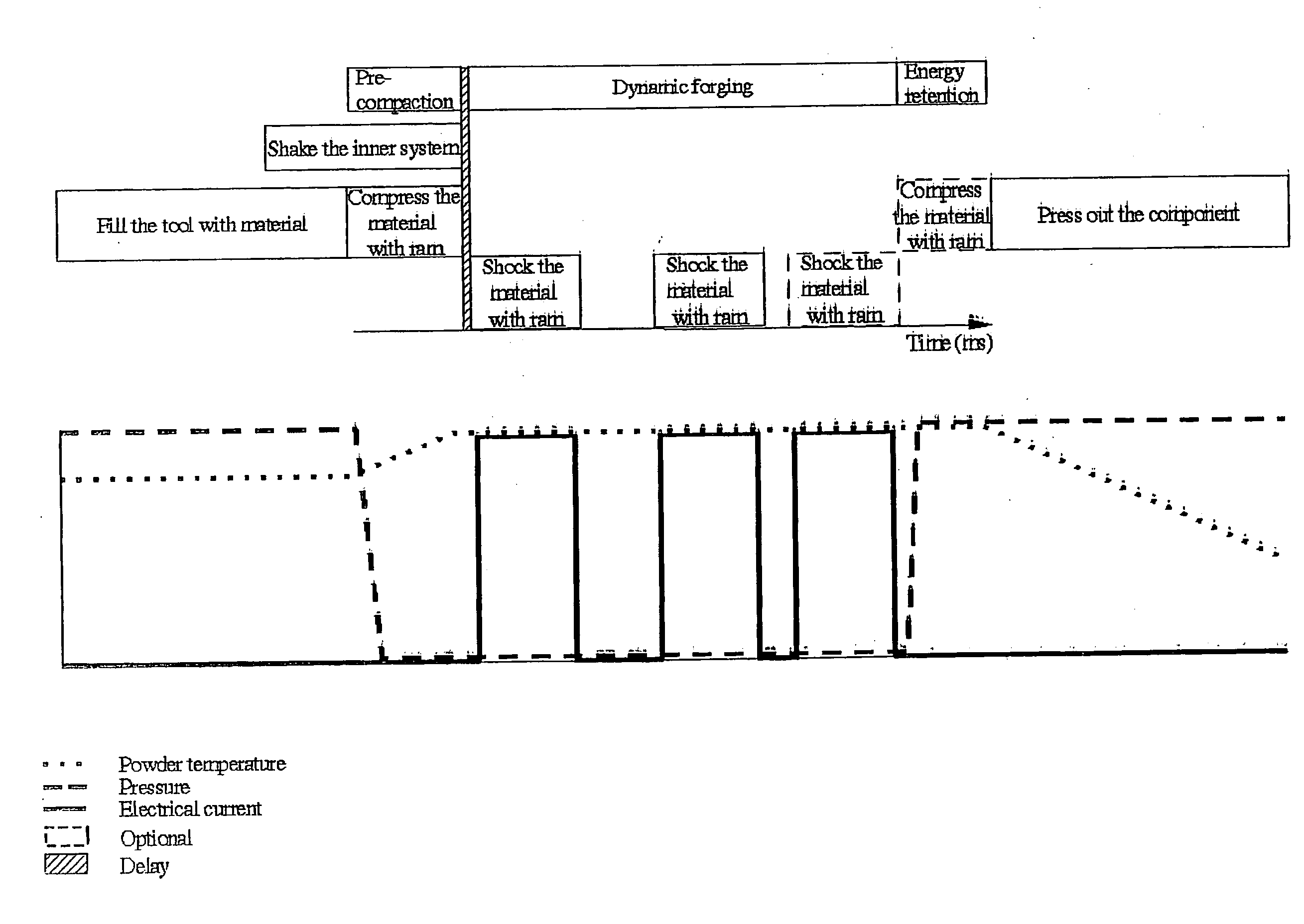
A method of producing a body from a particulate or solid material comprises filling a precompacting mould with the material, optionally vibrating the mould, pre-compacting the material and compressing it by at least one stroke with high kinetic energy in order to cause coalescence or high density of the material.

Description

[0001] The invention concerns a method of producing a body by coalescence or compaction to higher density. STATE OF THE ART [0002] In WO-A1-9700751, an impact machine and a method of cutting rods with the machine is described. The document also describes a method of deforming a metal body. The method utilises the machine described in the document and is characterised in that preferably metallic material either in solid form or in the form of powder such as grains, pellets and the like, is fixed preferably at the end of a mould, holder or the like and that the material is subjected to adiabatic coalescence by a striking unit such as an impact ram, the motion of the ram being effected by a liquid. The machine is thoroughly described in the WO document. [0003] In WO-A1-9700751, shaping of components, such as spheres, is described. A metal powder is supplied to a tool divided in two parts, and the powder is supplied through a connecting tube. The metal powder has preferably been gas-ato...

Claims


Application Information

Patent Timeline
IPC IPC(8): B21J7/02B21J7/22B21J7/28B21J7/34B22F3/087B30B11/02
CPCB21J7/02B21J7/22B21J7/28B21J7/34B22F3/087B22F2003/033B22F2999/00B29C2043/3618B30B11/027B22F3/14B22F3/105B22F3/093
Inventor OLSSON, KENTJIANGHO, LI
Owner OLSSON KENT
Learn More