Immersible thermal mass flow meter

a mass flow meter and immersion technology, applied in the field of mass flow meters, can solve the problems of increasing temperature between the encased heated sensor and the external surface of the housing, non-ideal behavior and measurement errors, and skin resistance creating a “drooping” effect, so as to improve the measurement quality and improve the quality of the device.

Active Publication Date: 2005-10-13
SIERRA INSTR
View PDF5 Cites 23 Cited by
  • Summary
  • Abstract
  • Description
  • Claims
  • Application Information

AI Technical Summary

Benefits of technology

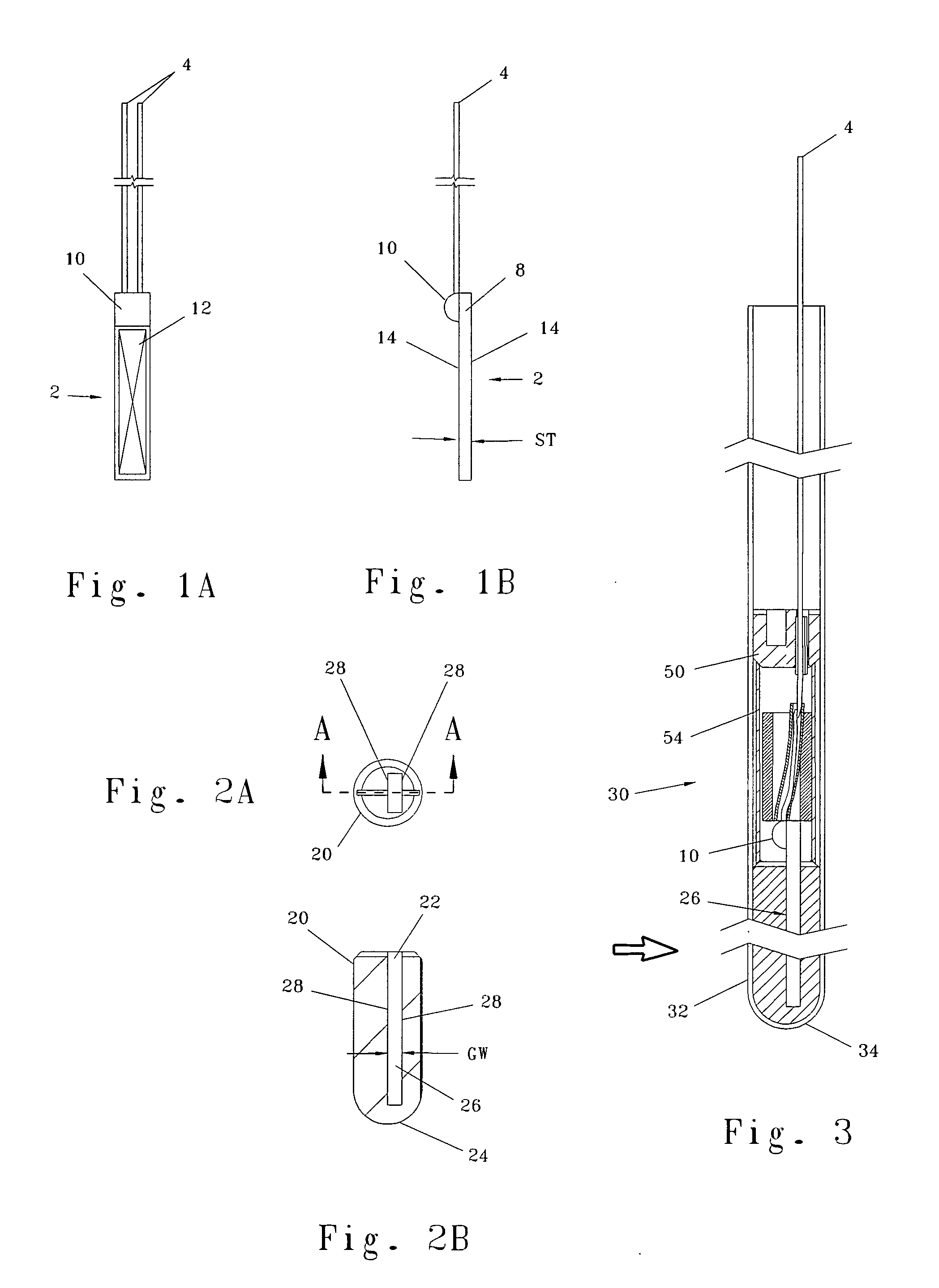
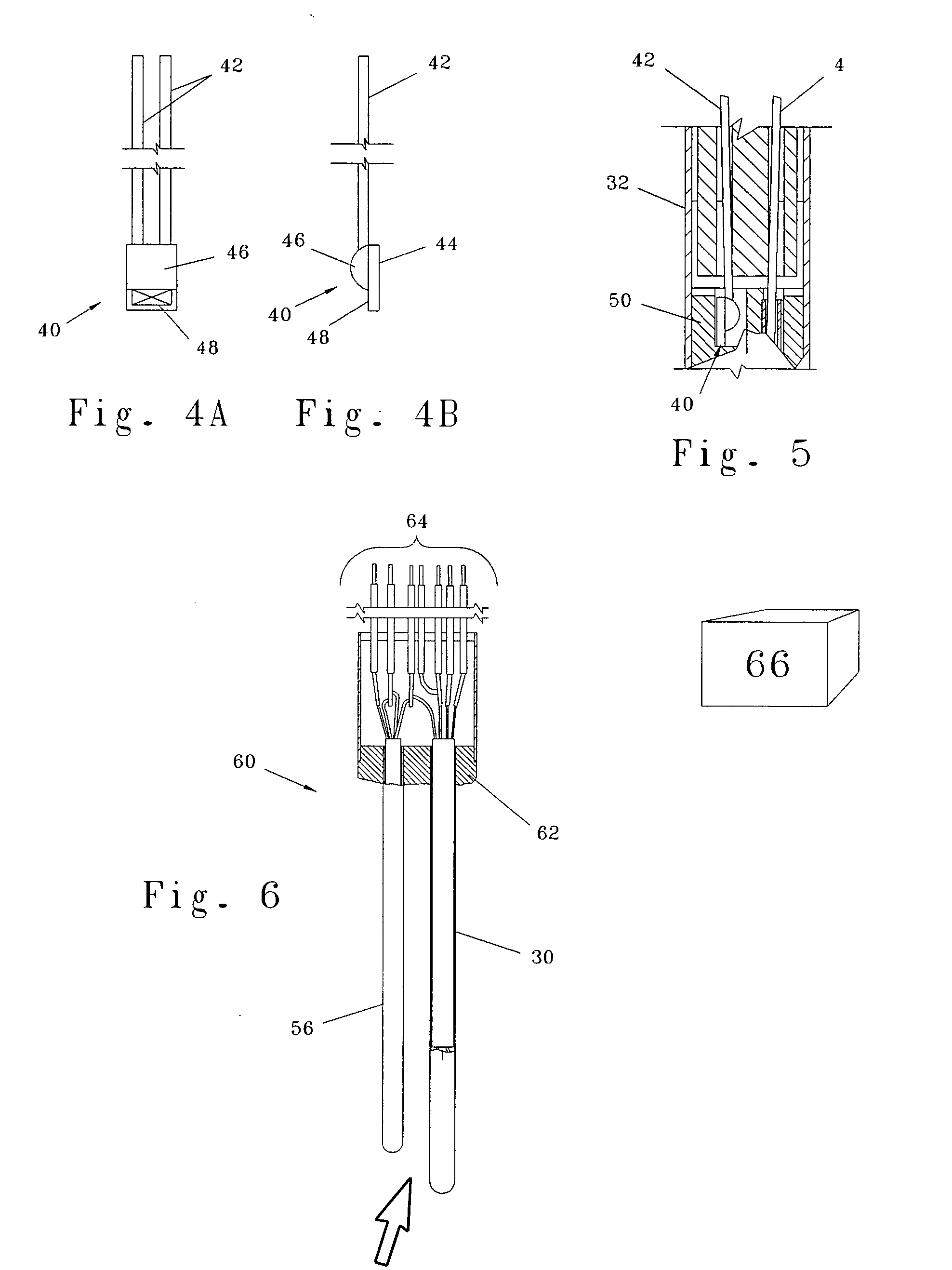
[0016] Where a thermal anemometer is desired for use in a given application, the quality of the device may be quite significant. The present invention offers a mode of device construction or packaging in connection with thin-film RTD sensors (TFRTD) that is able to leverage the cost advantage offered by such products, but still attains and impr

Problems solved by technology

Because the parts of the heated sensor of known thermal anemometers are not sufficiently reproducible dimensionally or electrically, known thermal anemometers require multi-point flow calibration of electrical output versus mass flow rate, usually in the actual fluid and with the actual ranges of fluid temperature and pressure of the application.
In such a system, “skin resistance” and stem conduction are two major contributors to non-ideal behavior and measurement errors in thermal anemometers constructed in this manner.
Skin resistance results in a temperature drop between the encased heated sensor and the external surface of the housing which increases as the electrical power supplied to the heated sensor increases.
Skin resistance creates a “droop” and decreased sensitivity in the power versus fluid mass flow rate calibration curve which is difficult to quantify and usually varies from meter to meter because of variations both in the parts of construction and in installation.
The ultimate result of these skin-resistance problems is reduced accuracy.
Furthermore, the use of a surrounding potting compound can create long-term measurement errors caused by aging and by cracking due to differential thermal expansion between the parts of the heated sensor.
If the ambient temperature changes, stem conduction changes, and measurement errors occur.
Similarly, stem conduction is responsible for errors in the

Method used


Image

  • Immersible thermal mass flow meter
  • Immersible thermal mass flow meter
  • Immersible thermal mass flow meter

Examples


Embodiment Construction

[0039] Before the present invention is described in detail, it is to be understood that this invention is not limited to particular variations set forth and may, of course, vary. Various changes may be made to the invention described and equivalents may be substituted without departing from the true spirit and scope of the invention. In addition, many modifications may be made to adapt a particular situation, material, composition of matter, process, process act(s) or step(s), to the objective(s), spirit or scope of the present invention. All such modifications are intended to be within the scope of the claims made herein.

[0040] Methods recited herein may be carried out in any order of the recited events which is logically possible, as well as the recited order of events. Furthermore, where a range of values is provided, it is understood that every intervening value, between the upper and lower limit of that range and any other stated or intervening value in the stated range is enc...


PUM


Abstract

A thermal anemometer or mass flow meter having temperature and flow velocity sensor elements is provided in which a thin film temperature sensor is provided in the heated sensor of the fluid velocity sensor element of the system. The thin-film sensor is captured at least partially within a spacer or interface member, the spacer being received within a housing. The thermal anemometer is constructed to offer sufficient precision and accuracy in its design to be suitable for sensitive scientific and industrial applications. This goal is achieved while using cost effective parts—as in the thin film temperature sensor(s)—in connection with a construction approach minimizing or eliminating gaps or other system configuration variability.

Description

FIELD OF THE INVENTION [0001] This invention relates to mass flow meters, particularly regarding their manufacture at decreased cost, yet of such quality for critical applications. BACKGROUND OF THE INVENTION [0002] The mass flow rate of a fluid (defined by its average velocity multiplied by its mass density multiplied by the cross-sectional area of the channel through which the flow travels) is a measured quantity of interest in the control or monitoring of most practical and industrial applications, such as any chemical reaction, combustion, heating, cooling, drying, mixing, fluid power, etc. Generally speaking, a thermal anemometer is used to measure the mass velocity at a point or small area in a flowing fluid—be it liquid or gas. The mass velocity of a flowing fluid is its velocity referenced to standard or normal temperature and pressure. The mass velocity averaged over the flow channel's cross-sectional area multiplied by the cross-sectional area is the standard or normal vol...

Claims


Application Information

Patent Timeline
IPC IPC(8): G01D21/00G01F1/68G01F1/684
CPCG01F1/684G01F1/6842
Inventor OLIN, JOHN
Owner SIERRA INSTR
Why Eureka
Try Eureka