High dynamic range pixel amplifier

a high-dynamic range, amplifier technology, applied in the field of semiconductor devices, can solve the problems of image distortion, limiting the dynamic range of the image sensor, and limiting the upper-end dynamic range, so as to achieve greater capacitance, lower capacitance, and greater capacitance

Active Publication Date: 2005-10-13
APTINA IMAGING CORP
View PDF6 Cites 183 Cited by
  • Summary
  • Abstract
  • Description
  • Claims
  • Application Information

AI Technical Summary

Benefits of technology

[0015] The pixel cell is capable of providing two or more different non-destructive readouts of the same image signal from the same integration. One readout is taken with the gate on, a second readout is taken with the gate off. This switchability allows the floating diffusion region to have a greater capacitance in the case of high-intensity light or a lower capacitance in the case of low-intensity light. The benefit of having a floating diffusion region with a greater capacitance when the incident light has high intensity is that it provides a lower conversion gain, and thus lower sensitivity readout. Conversely, the floating diffusion may have a lower capacitance when the incident light is of low intensity, providing a higher conversion gain, and thus higher sensitivity readout. The two readouts may be combined to provide a single pixel output signal having a desired level of conversion gain, or one of the pixel output signals can be discarded and the other used during image processing.

Problems solved by technology

The dynamic range is limited on an upper end by the charge saturation level of the sensor, and on a lower end by noise imposed limitations and / or quantization limits of the analog-to-digital converter used to produce the digital image.
When the dynamic range of an image sensor is too small to accommodate the variations in light intensities of the imaged scene, e.g., by having a low saturation level, image distortion occurs.
As a result, some pixels may saturate while others may provide a faint signal, limiting the dynamic range of the image sensor.

Method used


Image

  • High dynamic range pixel amplifier
  • High dynamic range pixel amplifier
  • High dynamic range pixel amplifier

Examples


Embodiment Construction

[0036] In the following detailed description, reference is made to the accompanying drawings which form a part hereof, and in which is shown by way of illustration specific embodiments in which the invention may be practiced. These embodiments are described in sufficient detail to enable those skilled in the art to practice the invention, and it is to be understood that other embodiments may be utilized, and that structural, logical and electrical changes may be made without departing from the spirit and scope of the present invention.

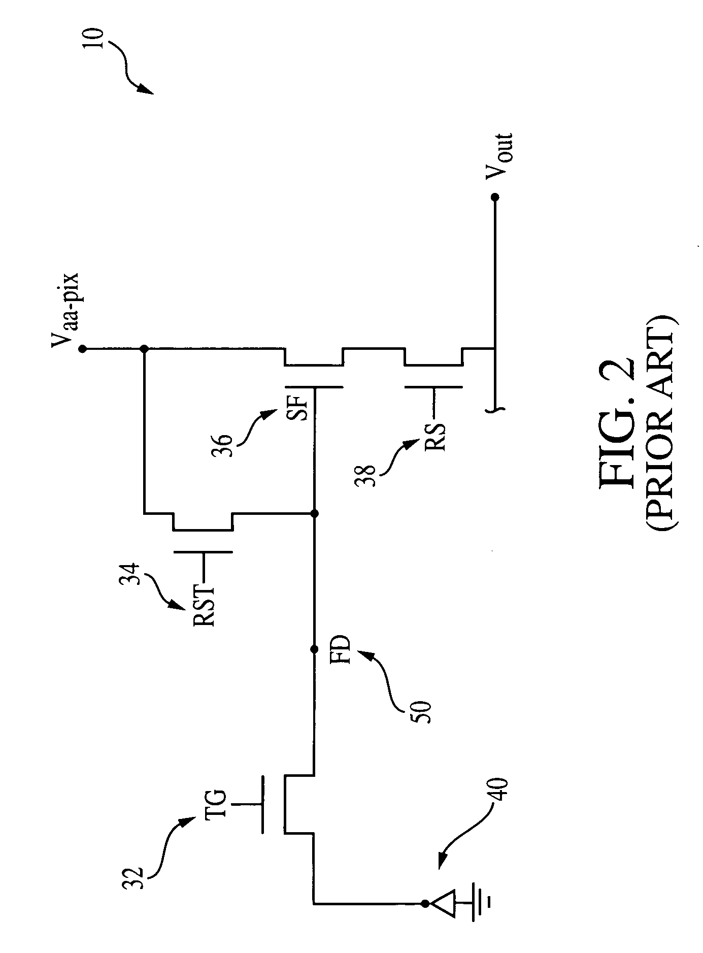
[0037] The term “pixel” refers to a photo-element unit cell containing a photoconversion device or photosensor and transistors for processing an electrical signal from electromagnetic radiation sensed by the photoconversion device. The pixels discussed herein are illustrated and described as inventive modifications to four transistor (4T) pixel circuits for the sake of example only. It should be understood that the invention is not limited to a four t...


PUM


Abstract

A pixel cell with increased dynamic range is formed by providing a floating diffusion region having a variable capacitance, controlled by at least one gate having source and drain regions commonly connected to the floating diffusion region. The gate has an intrinsic capacitance which, when the gate is activated, is added to the capacitance of the floating diffusion region, providing a low conversion gain readout. When the gate is off, the floating diffusion region capacitance is minimized, providing a high conversion gain readout. The gate may also be selectively switched to mid-level. At mid-level, a mid-level conversion gain, which is between the high and low conversion gains, readout is provided, but the gate still provides some capacitance to prevent the floating diffusion region from saturating.

Description

FIELD OF THE INVENTION [0001] The invention relates to the field of semiconductor devices and, in particular, to a high dynamic range pixel amplifier for an imager. BACKGROUND OF THE INVENTION [0002] A CMOS imager circuit includes a focal plane array of pixel cells, each cell includes a photosensor, for example, a photogate, photoconductor or a photodiode overlying a substrate for producing a photo-generated charge in a doped region of the substrate. A readout circuit is provided for each pixel cell and includes at least a source follower transistor and a row select transistor for coupling the source follower transistor to a column output line. The pixel cell also typically has a floating diffusion node, connected to the gate of the source follower transistor. Charge generated by the photosensor is sent to the floating diffusion region. The imager may also include a transistor for transferring charge from the photosensor to the floating diffusion node and another transistor for rese...

Claims


Application Information

Patent Timeline
Patent Type & Authority Applications(United States)
IPC IPC(8): H01L27/146H01L27/148
CPCH01L27/14603H01L27/14609H01L27/14806H04N3/155H04N5/335H04N5/3559H04N25/59H04N25/00
Inventor BOEMLER, CHRISTIAN
Owner APTINA IMAGING CORP
Why Eureka
Try Eureka