Modular fiber-based chirped pulse amplification system

a chirped pulse and fiber optic technology, applied in the direction of lasers, semiconductor lasers, active medium materials, etc., can solve the problems of not being able to guarantee the required stable operation of the laser, the difficulty of making such single-mode amplifiers has also been a limitation, and the method has not been described

Inactive Publication Date: 2005-10-13
IMRA AMERICA
View PDF36 Cites 126 Cited by
  • Summary
  • Abstract
  • Description
  • Claims
  • Application Information

AI Technical Summary

Benefits of technology

[0028] The invention extracts one or more chirped pulses from a series of such pulses using an acousto-optic deflector, and compensates for the detrimental effects on the spatial characteristics of the extracted chirped pulse caused by dispersion in that deflector. The instant invention has the additional advantage that the means to compensate for dispersion in the acousto-optic deflector can be used to compress the duration of the chirped pulse. This is accomplished by placing the AOM in proximity to a grating compressor.

Problems solved by technology

In U.S. Pat. No. 5,892,615 to Grubb, the use of bent single-mode amplifier fibers has been suggested; the difficulty in making such single-mode amplifiers has also been a limitation in such high power fiber amplifier systems.
These methods, however, have been only demonstrated for a pump diode with a single mode fiber coupler with the fiber Bragg grating written in a single mode fiber.
Thus far, no embodiment of these methods has been described for high power diode bundles with a multimode fiber coupler.
Difficulties lie in coupling cavities in stable coherence collapse regime with a multimode fiber pigtail and homogeneous Bragg grating fabrication in multimode fiber.
However, this solution faces a limit if the temperature-dependent variation of the gain fiber absorption is large, so that wavelength stabilization for the pump chip alone does not guarantee the required stable operation of the laser.
Thus the conventional concept described above is not applicable for stabilization of the gain fiber for stable output over a wide temperature range where: 1) wavelength locking using a device, e.g., a fiber Bragg grating, with a low temperature sensitivity in comparison with the pump device is not available, 2) the absorption spectrum of a gain medium has a large variation over temperature, so that a passively set wavelength does not provide the required stability of gain, 3) temperature sensing of the gain fiber is necessary for accurate gain stabilization.
However, the wide spectral bandwidth of the output of an ultrashort-pulse laser results in the spatial separation of the various wavelength components of such a pulse when subjected to the dispersive Bragg grating of an acousto-optic deflector.

Method used


Image

  • Modular fiber-based chirped pulse amplification system
  • Modular fiber-based chirped pulse amplification system
  • Modular fiber-based chirped pulse amplification system

Examples


second embodiment

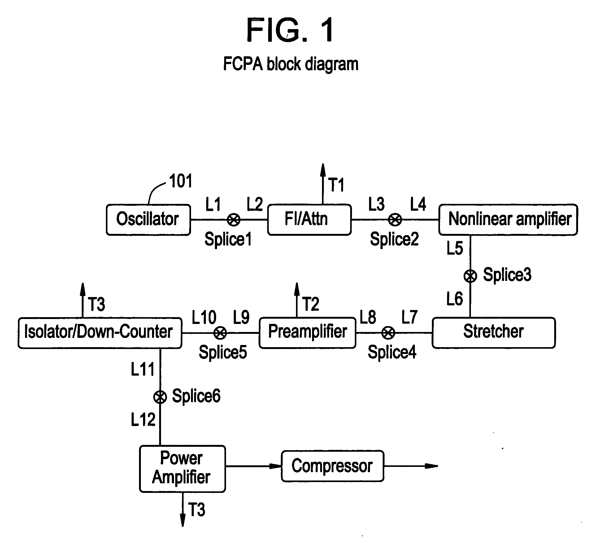
[0069] A block diagram of a second embodiment is shown in FIG. 11. The major difference in this embodiment is that the pulses are stretched before the first amplifier. Thus, in this design, nonlinear optical processes are minimized in the amplifiers. The advantage of this system is that reproducibility from system to system is easier to attain. However, the seed bandwidth from the oscillator has to be broader after the filter and before the stretcher (12-14 nm compared to 3 nm). The spectrum of the oscillator and after the first filter module is shown in FIGS. 12A and 12B. It is critical to have a filter between the oscillator and the rest of the system. At this point the spectral characteristics of each amplifier are not sufficiently the same to operate a system without a filter. The filter can be placed before the stretcher or after. If it is placed before the stretcher, then an attenuator module is used with this module. If the spectrum is filtered before the stretcher it is nece...

first embodiment

[0070] The spectrum from the preamplifier and the power amplifier are shown in FIGS. 13A and 13B. It will be noted that no noticeable nonlinear affects are taking place in the amplifiers. There is also some narrowing of the spectrum from gain narrowing. The spectrum of the output from the compressor is shown in FIG. 14A with the autocorrelation shown in FIG. 14B. As with the first embodiment, the pulse duration measured by the autocorrelator is 488 fs. This again gives a 345 fs pulse width assuming a Gaussian pulse shape. The output is 440 mW at a 200 kHz repetition rate. Thus a 2.2-μJ pulse is generated.

[0071] In order to be able to recompress the pulses, the spectrum of the output must be limited to 7-9 nm when a fiber stretcher and a bulk-grating compressor are used together. In order to get this spectral width the initial width needs to be broader since the amplifiers have some gain narrowing. In the case of the nonlinear amplifier, additional narrowing and filtering is necessar...


PUM


Abstract

A modular ultrafast pulse laser system is constructed of individually pre-tested components manufactured as modules. The individual modules include an oscillator, pre-amplifier and power amplifier stages, a non-linear amplifier, and a stretcher and compressor. The individual modules can typically be connected by means of simple fiber splices.

Description

TECHNICAL FIELD OF THE INVENTION [0001] The present invention relates to an ultrafast pulse source for pulse energies in the submicrojoule to millijoule range. The present invention uses state-of-art technologies to build an all fiber based chirped pulse amplification laser system suitable for industrial applications. BACKGROUND OF THE INVENTION [0002] Fiber lasers and amplifiers are promising pulse source candidates for industrial applications, due to their unique simplicity of construction. Large core fiber amplifiers and specifically large core diffraction limited multi-mode amplifiers (as described by M. E. Fermann and D. Harter, ‘Single-Mode Amplifiers and Compressors based on Multi-Mode Optical Fibers’, U.S. Pat. No. 5,818,630) (incorporated by reference herein) enable the amplification of optical signals to levels where applications such as micro-machining and laser marking become possible. See A. Galvanauskas et al., U.S. patent application Ser. No. 09 / 317,221 (incorporated ...

Claims


Application Information

Patent Timeline
Patent Type & Authority Applications(United States)
IPC IPC(8): H01S3/00H01S3/02H01S3/067H01S3/094H01S3/0941H01S3/098H01S3/10H01S3/102H01S3/13H01S3/16H01S3/23
CPCH01S3/005H01S3/0085H01S3/0064H01S3/0078H01S3/02H01S3/025H01S3/06712H01S3/06754H01S3/094011H01S3/0941H01S3/1028H01S3/1115H01S3/1305H01S3/1618H01S3/2316H01S3/06704H01S3/09415H01S3/10007H01S3/1301H01S5/0612H01S5/06804H01S3/0057H01S3/1001H01S3/13013H01S3/0014
Inventor LIU, ZHENLINCHO, GYU CHOENGU, XINHUAULRICH, OTHO E. JR.HARTER, DONALD J.
Owner IMRA AMERICA
Why Eureka
Try Eureka