
Low noise amplifier for wireless communications

a wireless communication and low noise technology, applied in amplifiers, amplifiers with semiconductor devices only, amplifiers with semiconductor devices, etc., can solve the problems of low noise, bulky filters, and less attractive filters for use in next generation receivers, and achieve low noise, low noise characteristics, and cancelling high frequency leakage

Inactive Publication Date: 2005-10-13
NEOREACH INC
View PDF28 Cites 40 Cited by
  • Summary
  • Abstract
  • Description
  • Claims
  • Application Information

AI Technical Summary

Benefits of technology

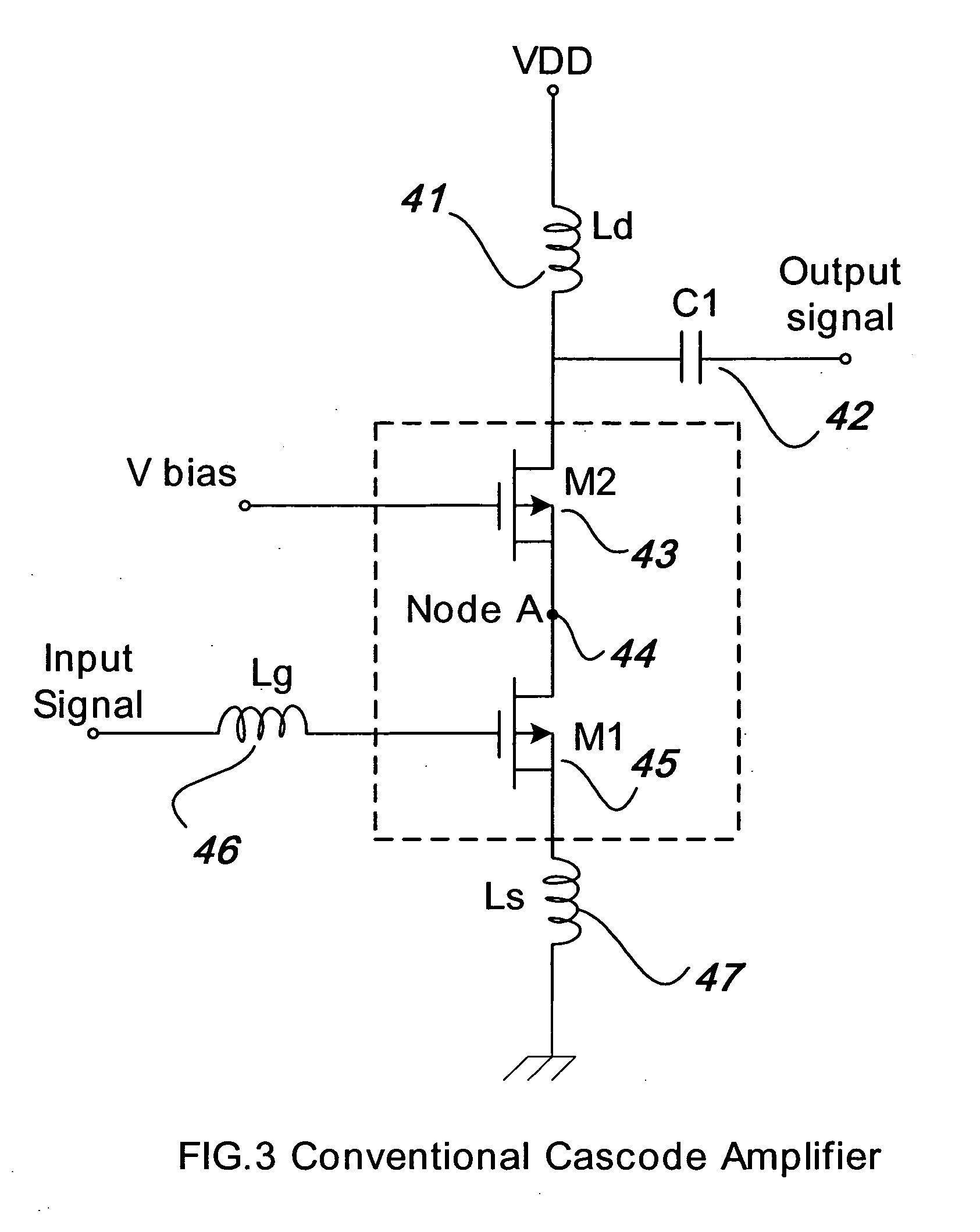
[0017] The present invention provides a LNA (Low Noise Amplifier) for use at radio frequencies in a wireless communication system, the amplifier preferably being used in an early stage of the wireless receiver and having a low noise characteristic. In one embodiment, the amplifier has a cascode configuration and includes an added inductor at a node between the two active elements to cancel parasitic capacitance and thereby cancel high frequency leakage.
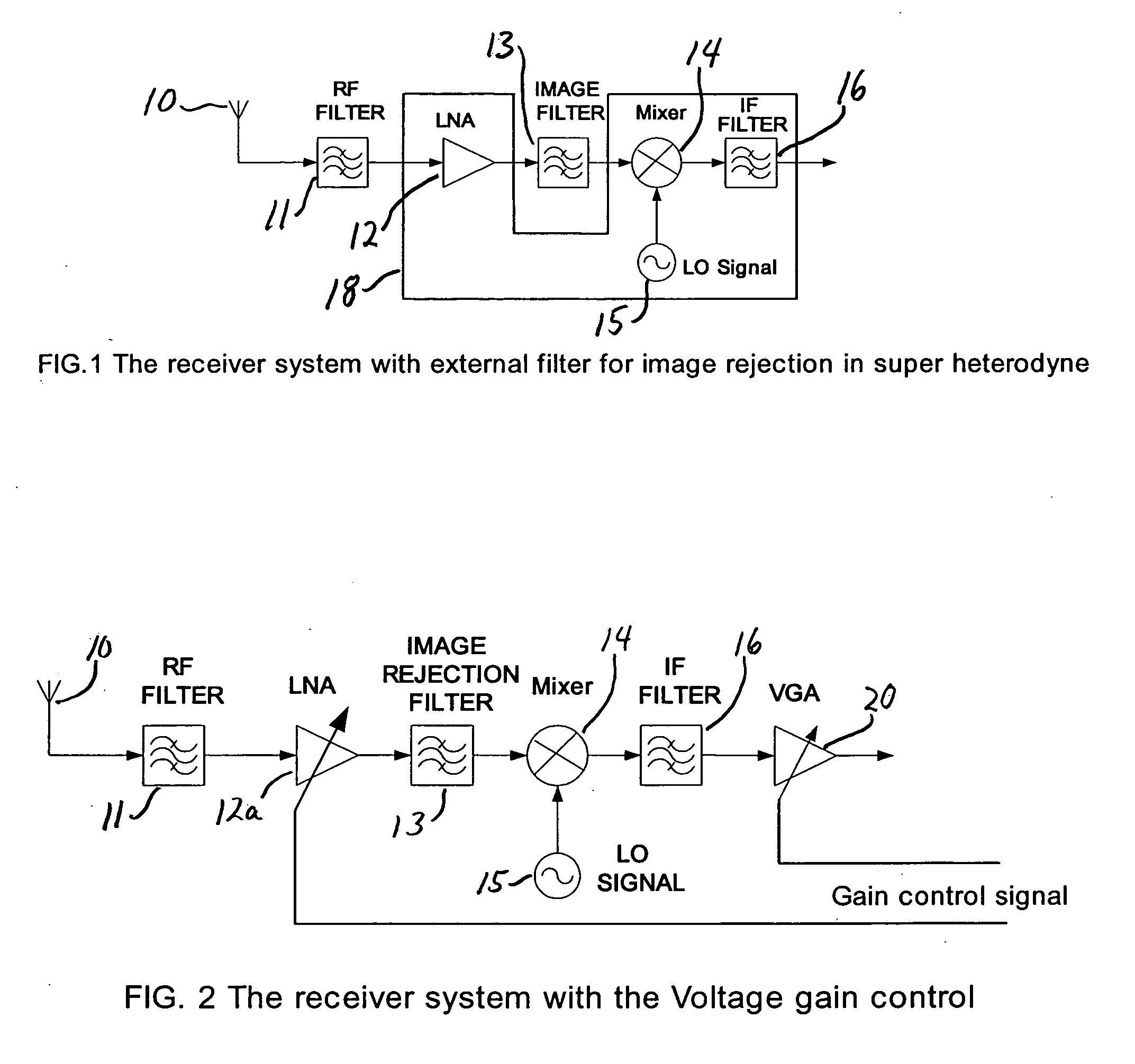
[0019] In yet further embodiments, the present low noise amplifier includes an added gain controller to simultaneously provide, in a preferred embodiment, image rejection and gain control functions in a low noise amplifier. The gain controller is provided by an active element, such as a FET (Field Effect Transistor) at the gate of which is connected a control signal. An added benefit of the preferred embodiment is that noise contributions are reduced compared to the core LNA cascode amplifier device. In addition, the gain control improves the input linearity of front-end circuit in the presence of large signals.

Problems solved by technology

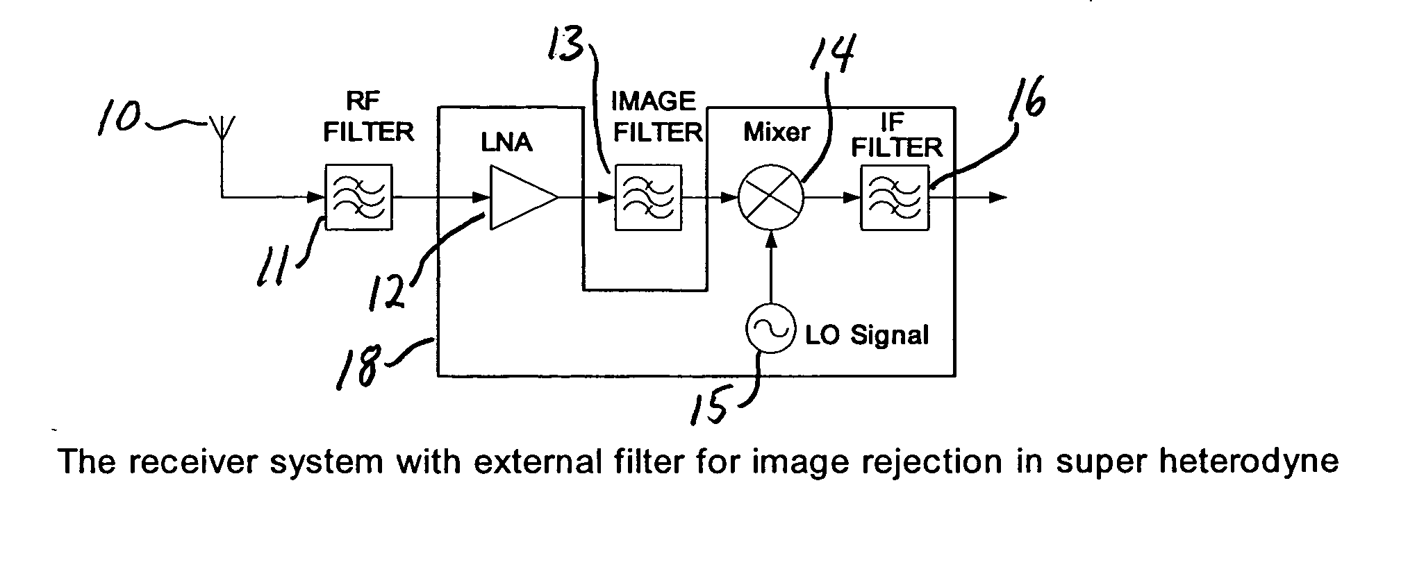
In super-heterodyne receivers, the image frequency presents a problem because the image frequency is superimposed on the desired signal.
However, the high cost and large size of such separate bandpass filters make these filters less attractive for use in the next generation receivers.
The current, off-chip passive filters, such as surface acoustic wave filters or ceramic filters, are used for image frequency rejection, but these bulky filters are the major impediment to raising the level of integration of the radio frequency circuit since they cannot be easily integrated.
Systems using these filters have a relatively high cost and large size.
When an inductor having a high quality factor is used for this source degeneration function, the result is that the amplifier has good noise performance.

Method used


Image

  • Low noise amplifier for wireless communications
  • Low noise amplifier for wireless communications
  • Low noise amplifier for wireless communications

Examples


Embodiment Construction

[0029] The present invention provides an improvement over the conventional cascode amplifier that is used in a radio frequency receiver communication system. The present low noise amplifier eliminates the need for an external image rejection filter from the receiver circuit so that there is no longer a requirement for an off-chip filter for image rejection. This enables a higher level of integration, a more compact circuit and lower costs.

[0030] The circuit of one embodiment of the present low noise amplifier is shown in FIG. 4. The amplifier, like the amplifier of FIG. 3, has two FETs (Field Effect Transistors) connected to one another. Here, FETs 52 and 57 are provided. The present invention recognizes that the low noise amplifier of FIG. 3 generates a signal leakage due to the parasitic capacitance of node 44, also denoted node A in the figure. In order to solve this signal leakage problem, the first improvement of the LNA topology provides a resonance inductor connected at node...


PUM


Abstract

A low noise amplifier is provided for the receiver of a wireless communications system. The amplifier incorporates an image rejection function by incorporating a notch filter formed by an inductor and capacitor connected at a node between two active elements of the amplifier. The amplifier also incorporates a gain control function by adding a further active element connected to, on one hand, a node between the inductor and capacitor and, on the other hand, a voltage supply. A gain control signal is connected to the control input of the further active element has an input connected to a feedback lead of the receiver to provide the gain control.

Description

BACKGROUND OF THE INVENTION [0001] 1. Field of the Invention [0002] The present invention relates generally to an amplifier for use in a wireless communication system, and in particular to a low noise amplifier for use in a radio frequency receiver. [0003] 2. Description of the Related Art [0004] With the explosive growth in the commercial wireless telecommunications market, a greater need is seen for lower cost and more highly integrated telecommunications equipment. Integrated semiconductor devices provide the possibility of meeting both needs. For example, silicon based devices may provide the necessary characteristics to address a wide range of applications. CMOS (Complementary Metal Oxide Semiconductor) technology is becoming feasible for high frequency analog applications that were traditionally built with more expensive technologies such as bipolar devices. Sub-micrometer CMOS technologies now exhibit sufficient performance for RF (Radio Frequency) applications in a few gigah...

Claims


Application Information

Patent Timeline
Patent Type & Authority Applications(United States)
IPC IPC(8): H04B1/04H04B1/16H04B1/28
CPCH04B1/28H03F1/223H04B2001/0408H03F3/24
Inventor KANG, DONG KYUNGORDON, KURTWRIGHT, JAY
Owner NEOREACH INC
Learn More