Ordered particle structures and methods of making same

a technology of ordered mixture and particle structure, which is applied in the direction of fuels, weaving, explosives, etc., can solve the problems of reducing the dissolution rate, reducing the interaction force between, and no prior art mechanism that yields ordered adhesion, etc., and achieves the effect of enhancing the flow properties and cost effectiv

Inactive Publication Date: 2005-10-13
NEW JERSEY INSTITUTE OF TECHNOLOGY
View PDF9 Cites 24 Cited by
  • Summary
  • Abstract
  • Description
  • Claims
  • Application Information

AI Technical Summary

Benefits of technology

[0011] It is a further object of the present invention to permit higher solids loading where desirable.
[0013] It is a further object of the present invention to provide novel, versatile and cost effective processes for coating components with curable polymeric materials in order to enhance their flow properties.

Problems solved by technology

To date, no prior art mechanism has been established that yields ordered adhesion.
In the pharmaceutical industry, any addition of binder / glue in the ordered mixing process to enhance the adhesion between small drug particles and coarser carrier particles may reduce the dissolution rate and thus the bioavailability of the final dosage form.
As a result, the relatively weak interactive forces between the guest (drug) and host (carrier excipient) particles tend to segregate by frictional attrition during subsequent solids handling and processing steps.
An ordered system has a greater stability than a random system due to the particle interaction; but once this interaction is disturbed, the segregation pattern of an ordered mixture may be more unpredictable than a random mixture.
For some mixtures, stoichiometry is very important, however, currently there is no process or method available for creating ordered, stoichiometric mixtures.
It is also believed that there is currently no process available for simultaneously coating fine as well as coarser particles and clustering particles to form an ordered mixture.

Method used


Image

  • Ordered particle structures and methods of making same
  • Ordered particle structures and methods of making same
  • Ordered particle structures and methods of making same

Examples


example 2

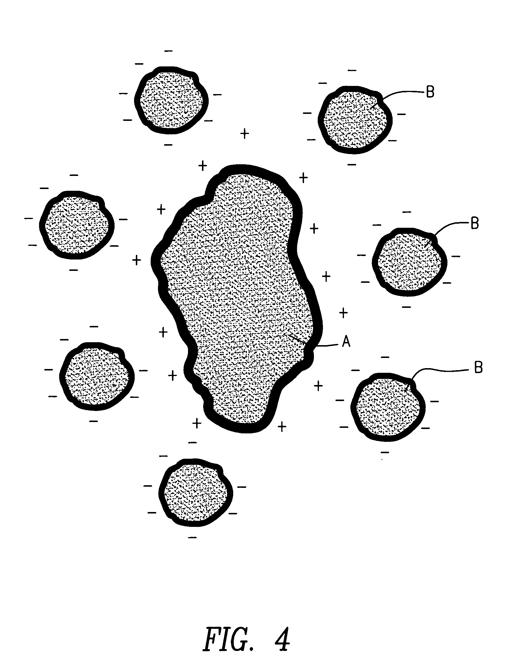
[0097] Particle A is acetaminophen and B is powdered poly(vinyl acetate). The oppositely charged polymer particles surround and agglomerate on the drug. The formulation is employed to modulate the pharmacological release of the active drug.

[0098] The advantages of triboelectric clustering according to the present invention are that no viscous liquid binder is required, A and B are in close proximity, the combined powders A and B are flowable and there is a degree of control of the proportions of B to A (“stoichiometry”).

Magnetic Clustering

[0099] As is well known, a collection of iron particles can be magnetized and will adhere to one another. This is an unstructured array of one type of particle. Typically, the powder becomes an agglomerate and does not flow. This is undesirable for the present invention in which a flowable powder is preferred. Magnetic particles with permanent magnetic moments (ferrites, iron powder, etc.) attract one another indiscriminantly. To overcome this,...

example 1

[0102]“A” is a 100 μm diameter particle of barium ferrite. “B” is an organic polymer containing or coated with numerous nanoparticles of SPM ferrous ferrite, Fe3O4.

[0103] The barium ferrite is premagnetized, and thus retains a remanent magnetism. This is the attractor for particles of B which cluster around the A particle, held by magnetostatic forces.

[0104] If A is not an intrinsically magnetic material, it can be coated with a layer of attached material containing a ferrimagnet such as barium ferrite.

[0105] Magnetic clustering in accordance with the foregoing method can be used to combine A and B into a dry flowable composite suitable for the manufacture of many materials including energetics and explosives.

Chemical Reaction or Fusion

[0106] Now referring to FIG. 7, clustering may be achieved by heating a charge of different sized particles A and B and polymer D above the glass transition temperature of the coated polymer to form fusion points 10 between particles. Alternativ...

experiment 1

[0159] Now referring to FIGS. 14A and 14B SEMs of uncoated KCl (about 200 μm) show cubic crystals with surface defects. Now referring to FIGS. 14C and 14D SEM photographs of uncoated dechlorane (about 10 μm) show particles of irregular shape and size. Now referring to FIGS. 14E and 14F, particle size distributions for dechlorane and pure KCl are shown. The pure KCl has a mean of 284 μm.

[0160] The binder employed in these experiments was Smooth-Cast 327™, a two component system with an A:B mixed ratio of 1:1 pbv. The shrinkage of Smooth-Cast 327™ is 0.35% with a specific gravity of equal volume mixture A:B of 1.60 g / cc. The viscosity of the Smooth-Cast 327™ mixture increases with time. Now referring to FIG. 14G a graphical representation of the changes of viscosity with time for Smooth-Cast 327™ is disclosed.

[0161] Employing the SPA method of the present invention, a particle mixture of KCl and Dechlorane Plus was coated. 240 g of KCl was preblended with 3 ml of equal volume of A a...


PUM


Abstract

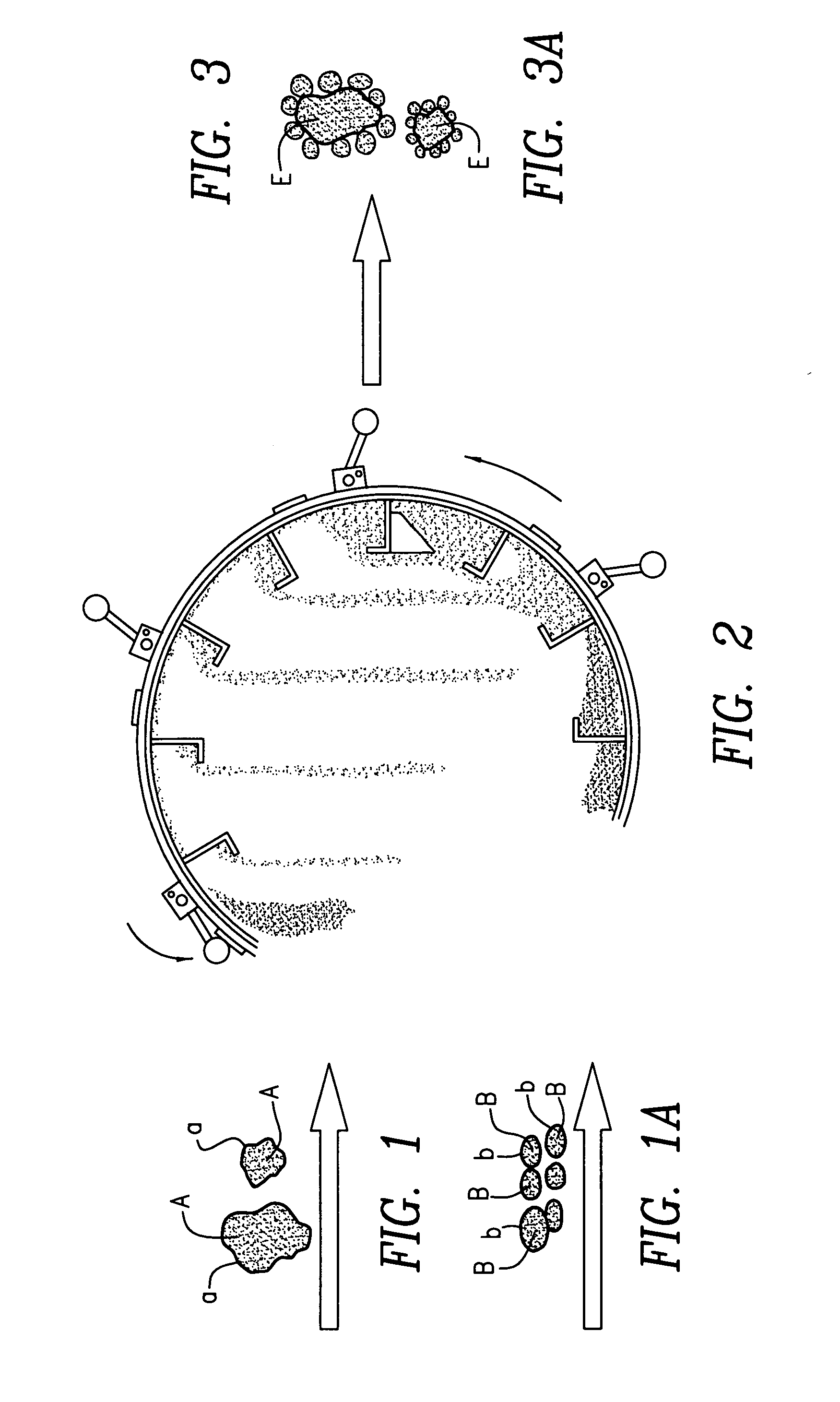
Techniques and methods of formation of ordered mixtures of particles by “clustering”. Clustering comprises local “structuring” consisting of a large “host” and smaller “guest” particles by various techniques. Small amounts of polymer are coated onto solid particles by various means. In one embodiment, an ordered mixture is created wherein the material that is of lesser quantity is of small particle size (the “B” particles) and the “A” particles are of larger size. The “B” particles are then coated onto a single A particle. By creating this ordered structure, each composite particle has the proper or stoichiometric amount of all ingredients. This dry composite material produced is appropriately used in various applications such as pharmaceutical formulations in the form of tablets, capsules, oral suspensions, inhalant, parenteral formulations and the like; energetics manufacture such as but not limited to explosives, propellants and pyrotechnics; agricultural products including but not limited to fertilizers, herbicides and pesticides; nutritional supplements and the like.

Description

FIELD OF THE INVENTION [0001] The present invention relates to techniques and processes for forming ordered mixtures of particles. BACKGROUND [0002] The terms “ordered mixing” and “ordered mixtures” formed by such mixing processes were coined to describe the mixing of cohesive, interactive particulate systems, in differentiation to the traditional randomization mixing process of comparatively coarse, free-flowing, non-interacting particulate systems. Ordered Powder Mixing, Nature, Volume 262, Jul. 15, 1976, Pages 262-263, Chee Wai Yip, John A. Hersey; Ordered mixing: A new concept in powder mixing practice, Powder Technology, Volume 11, Issue 1, January-February 1975, Pages 41-44 J. A. Hersey. The basic principle of ordered mixing is that fine particles will adhere, especially to larger particles. The adhesion forces involved may be electrostatic, van der Waals, or surface tensional. Coarser components assist in the mixing process by breaking down agglomerates of the fine powder, th...

Claims


Application Information

Patent Timeline
Patent Type & Authority Applications(United States)
IPC IPC(8): C06B21/00C06B45/02C08J3/20C08K7/00C10L5/00D03D23/00
CPCC06B21/0025C08J3/20C06B45/02C06B21/0083
Inventor GOGOS, COSTASYOUNG, MING-WANDAVE, RAJESHPFEFFER, ROBERTDAVIDSON, THEODORETODD, DAVIDQIAN, BAINIANYANG, JUN
Owner NEW JERSEY INSTITUTE OF TECHNOLOGY
Why Eureka
Try Eureka