Reaction system for growing a thin film

Active Publication Date: 2005-11-03
ASM IP HLDG BV
View PDF6 Cites 391 Cited by
  • Summary
  • Abstract
  • Description
  • Claims
  • Application Information

AI Technical Summary

Benefits of technology

[0010] To prevent the vapor phase reactants from mixing, ALD reactors may include an “inert gas valving” or a “diffusion barrier” arrangement in a portion of a supply conduit to prevent flow of reactant from a reactant source to the reaction chamber during the purge step. Inert gas valving involves forming a gas phase, convective barrier of a gas flowing in the opposite direction to the normal reactant flow in the supply conduit. See T. Suntola, Handbook of Crystal Growth III, Thin Films and Epitaxy, Part B: Growth Mechanisms and Dynamics, ch. 14, Atomic Layer Epitaxy, edited by D. T. J. Hurle, El

Problems solved by technology

Although such prior art arrangements have been successful in preventing vapor phase reactants from mixing, these techniques do have certain disadvantages.
Such arrangem

Method used


Image

  • Reaction system for growing a thin film
  • Reaction system for growing a thin film
  • Reaction system for growing a thin film

Examples


Embodiment Construction

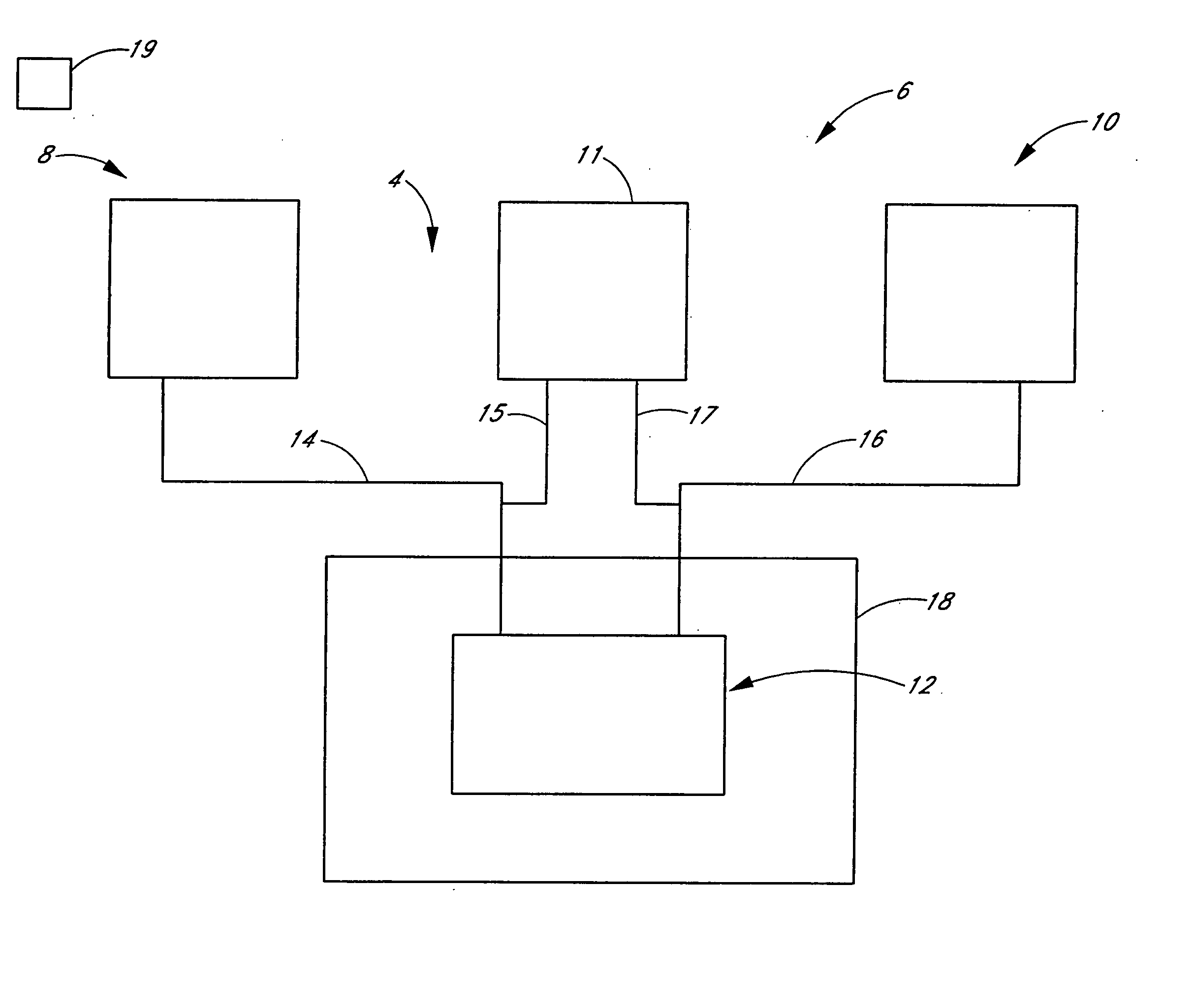
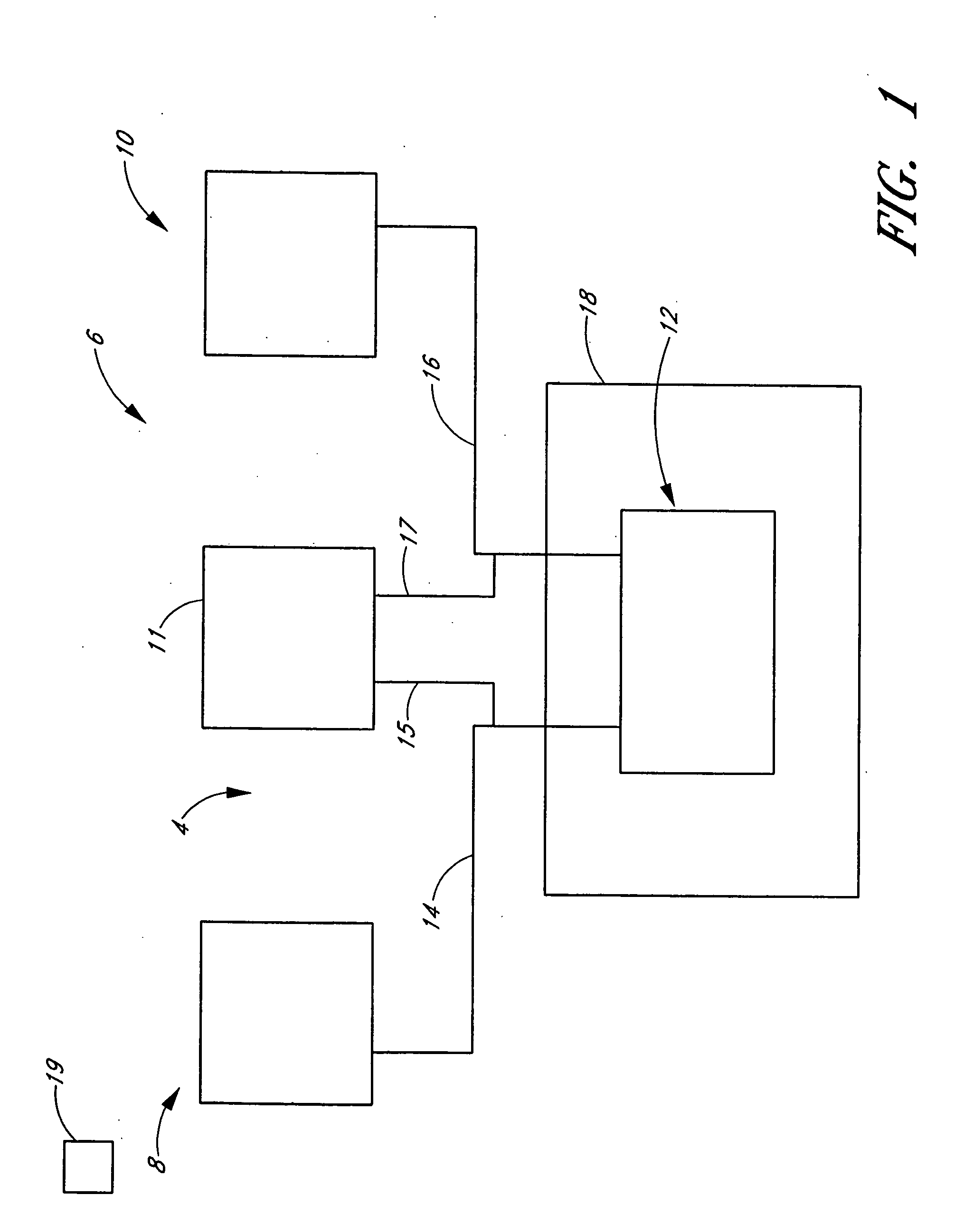
[0028]FIG. 1 is a schematic illustration of an exemplary embodiment of a processing system 6 comprising a vapor supply system 4 and vapor phase reactor 12. The vapor supply system 4 is configured to selectively supply one or more vapor phase reactants and a purging gas (e.g., an inactive or inert gas) to the reactor 12. In the illustrated embodiment, the vapor supply system 4 comprises a first source apparatus 8 and a second source apparatus 10 for selectively feeding a first and a second vapor phase reactant into the reactor 12. In one embodiment, the reactant (not shown) may be liquid or solid under standard (i.e., room temperature and atmospheric pressure) conditions. Such a reactant may be vaporized within a reactant source vacuum vessel, which may be maintained at or above a vaporizing temperature within a reactant source chamber. In such embodiments, the vaporized reactant may be transported with a carrier gas (e.g., an inactive or inert gas) and then fed into the reactor 12 t...


PUM

PropertyMeasurementUnit
Fractionaaaaaaaaaa
Fractionaaaaaaaaaa
Fractionaaaaaaaaaa

Abstract

A reactor defines a reaction chamber for processing a substrate. The reactor comprises a first inlet for providing a first reactant and to the reaction chamber and a second inlet for a second reactant to the reaction chamber. A first exhaust outlet removes gases from the reaction chamber. A second exhaust outlet removes gases from the reaction chamber. A flow control system is configured to alternately constrict flow through the first and second exhaust outlets. The reactor chamber is configured to for a diffusion barrier within the reaction chamber.

Description

PRIORITY INFORMATION [0001] This application claims the priority benefit under 35 U.S.C. § 119(e) of Provisional Application 60 / 580,498, filed Jun. 17, 2004, Provisional Application 60 / 573,711, filed May 21, 2004 and Provisional Application 60 / 515,237 filed Oct. 29, 2003 and the entire contents of these applications are hereby incorporated by reference herein.BACKGROUND OF THE INVENTION [0002] 1. Field of the Invention [0003] The present invention relates to equipment for chemical processes. In particular, the present invention relates to equipment for growing a thin film in a reaction chamber. [0004] 2. Description of the Related Art [0005] There are several vapor deposition methods for depositing thin films on the surface of substrates. These methods include vacuum evaporation deposition, Molecular Beam Epitaxy (MBE), different variants of Chemical Vapor Deposition (CVD) (including low-pressure and organometallic CVD and plasma-enhanced CVD), and Atomic Layer Epitaxy (ALE), which ...

Claims


Application Information

Patent Timeline
IPC IPC(8): C23C16/44C23C16/455C25F1/00F26B3/00H01L21/00
CPCC23C16/4412H01L21/67017C23C16/45591C23C16/45548
Inventor SHERO, ERIC J.VERGHESE, MOHITH E.
Owner ASM IP HLDG BV
Why Eureka
Try Eureka