High frequency plasma generator and high frequency plasma generating method

a plasma generator and high frequency technology, applied in the direction of plasma technique, chemical vapor deposition coating, coating, etc., can solve the problem of difficult uniform distribution of the thickness of the film, and achieve the effect of improving the cutting performance of the laser in the laser etching step in a process, and improving the performance of the electric cell

Inactive Publication Date: 2005-11-03
MITSUBISHI HEAVY IND LTD
View PDF8 Cites 15 Cited by
  • Summary
  • Abstract
  • Description
  • Claims
  • Application Information

AI Technical Summary

Benefits of technology

[0040] By the high-frequency plasma generating apparatus and in the high-frequency plasma generating process according to the present invention, a first high-frequency voltage is applied to a feeding point disposed on a lateral portion of the discharge electrode, and a second high-frequency voltage is applied to a feeding point disposed on another lateral portion of the discharge electrode, the second high-frequency voltage having the same frequency as that of the first high-frequency voltage and having a phase which varies with a low-frequency signal, which is modulated by a predetermined modulation signal. Therefore, the high-frequency plasma generating apparatus and high-frequency plasma generating process according to the present invention are more effective in achieving uniformity in the thickness of a film formed on a substrate having a large area than conventional apparatuses.
[0041] Accordingly, an apparatus according the present invention when used to produce a thin film of amorphous silicon semiconductor for an electric cell, for example, contributes greatly to improvement in the performance of the electric cell since the thickness of the film can be made uniform. In addition, cutting performance of laser in a laser etching step in a process can be greatly improved, which also contributes to improvement in the performance of the electric cell.
[0042] In addition, since the film thickness can be made uniform according to the present invention, a pattern such as interference fringes does not appear, and therefore the present invention is advantageous in improving the appearance of products.
[0043] Furthermore, the process for cleaning a high-frequency plasma generating apparatus according to the present invention is effective in allowing the apparatus to self-clean without causing overetching. Moreover, since uniformity in cleaning is improved, the process has effects of shortening time for cleaning and contributing to minimizing influence on the distribution of the formed film before and after cleaning.

Problems solved by technology

When the phase modulation angle was fixed as above, it was difficult to uniformly distribute the thickness of a film.

Method used


Image

  • High frequency plasma generator and high frequency plasma generating method
  • High frequency plasma generator and high frequency plasma generating method
  • High frequency plasma generator and high frequency plasma generating method

Examples


Embodiment Construction

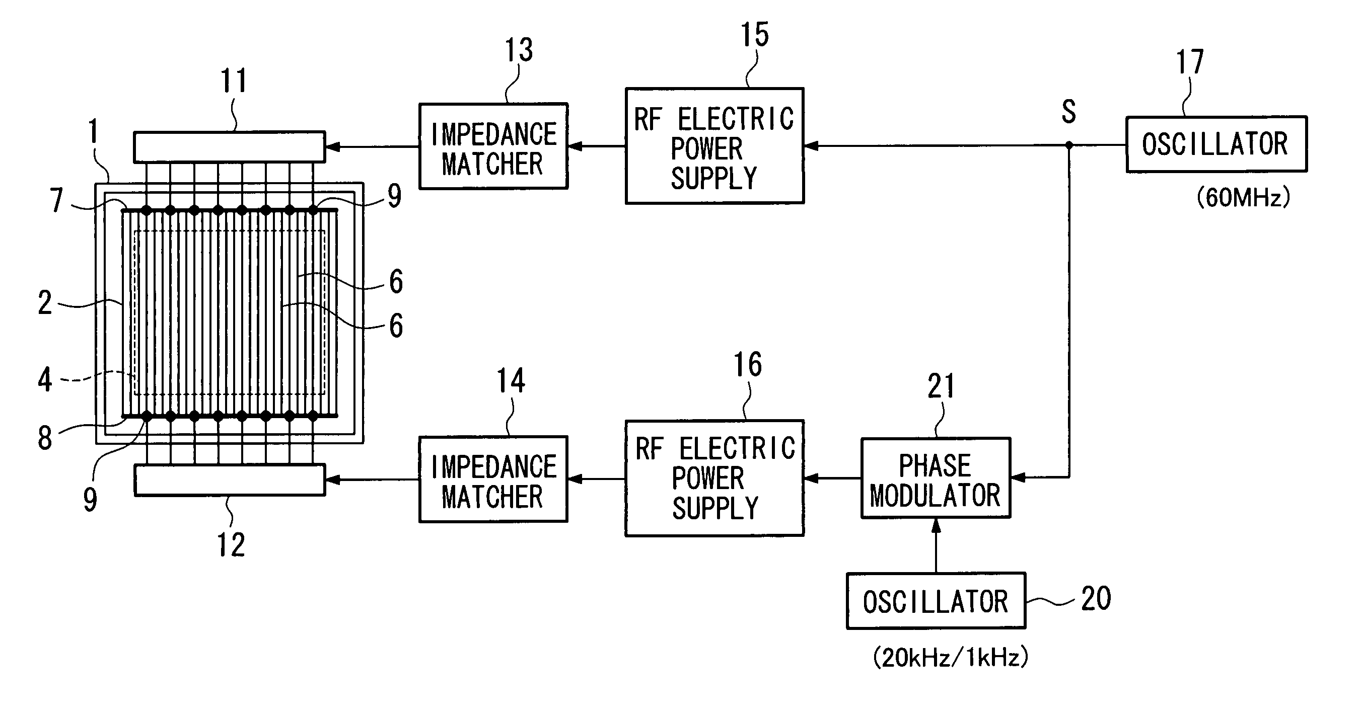
[0052] An embodiment of the present invention will be described below by referring to the drawings. FIG. 1 is a block diagram showing a structure of a high-frequency plasma generating apparatus according to this embodiment. The same reference numerals as those in FIG. 5 are assigned in FIG. 1 to the parts which are structurally the same as those in FIG. 5, and explanations of such parts are omitted.

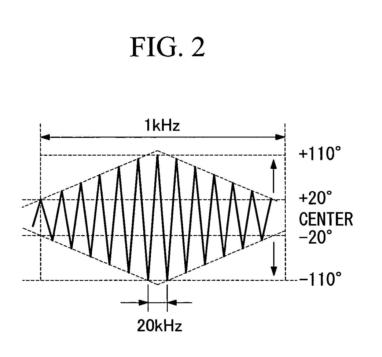
[0053] The high-frequency plasma generating apparatus according to this embodiment differs from the apparatus as shown in FIG. 5 in that an oscillator 20 and a phase modulator 21 deal with not only simple triangle waves or the like, but also arbitrarily modulated waveforms. The oscillator 20 is a circuit which generates a signal in a triangle wave with a frequency of 20 KHz as shown in FIG. 2, the signal having been subjected to amplitude modulation using a triangle wave with a frequency of 1 KHz. The phase modulator 21 is a circuit which modulates the phase of an output signal S (60 MHz...


PUM

PropertyMeasurementUnit
internal pressureaaaaaaaaaa
distanceaaaaaaaaaa
temperatureaaaaaaaaaa

Abstract

An object is to provide a high-frequency plasma generating apparatus and process which can further advance uniformity of the thickness of a film on a substrate with a large area in comparison with conventional apparatuses. In a reaction chamber (1), a ground electrode (3) is disposed, and a discharge electrode (2) is disposed opposite to the ground electrode (3). A substrate (4) as a processing object is placed in close contact with the ground electrode (3). A high-frequency voltage is applied to the discharge electrode (2) so as to generate plasma between the ground electrode and the discharge electrode. An RF electric power supply (15) generates a first high-frequency voltage, and outputs the generated voltage on feeding points (9) disposed on a lateral portion of the discharge electrode (2). An RF electric power supply (16) generates a second high-frequency voltage, and outputs the generated voltage on feeding points (9) disposed on another lateral portion of the discharge electrode (2). Here, the second high-frequency voltage has the same frequency as that of the first high-frequency voltage and has a phase which varies with a low-frequency signal, which is modulated by a predetermined modulation signal.

Description

TECHNICAL FIELD [0001] The present invention relates to high-frequency plasma generating apparatuses and high-frequency plasma generating processes, which can be applied to formation of films of semiconductors useful in solar sells, thin-film transistors, or the like, such as amorphous silicon, microcrystalline silicon, polycrystalline thin-film silicon, and silicon nitride, or which can be applied to etching of semiconductor films. BACKGROUND ART [0002]FIG. 5 shows an example of a conventional high-frequency plasma generating apparatus. FIG. 6 is a cross-sectional view showing a reaction chamber 1 of the same apparatus. The high-frequency plasma generating apparatus shown in these figures can be used for production of a thin film of amorphous silicon semiconductor for solar cells. [0003] The inside of the reaction chamber 1 shown in FIG. 5 is equipped with a ladder-shaped electrode 2 as a discharge electrode and a ground electrode 3. The reaction chamber 1 is made gastight, to whic...

Claims


Application Information

Patent Timeline
Patent Type & Authority Applications(United States)
IPC IPC(8): C23C16/509C23F1/00H05H1/46H01J37/32H01L21/205H01L21/3065
CPCH01J37/32155H01J37/32091
Inventor KAWAMURA, KEISUKEYAMADA, AKIRAMASHIMA, HIROSHITAKEUCHI, YOSHIAKI
Owner MITSUBISHI HEAVY IND LTD
Why Eureka
Try Eureka