
Method and device for the production of an antireflective coating, antireflective coating, and antireflective-coated substrate

a technology of anti-reflective coating and production method, applied in the direction of solar heat devices, solar ray transmission and prevention of heat radiation, coatings, etc., can solve the problems of high production cost of plate glass coated with the known method, material or chemical elements, and considerable cost of vacuum coating procedures

Inactive Publication Date: 2005-11-03
INTERFLOAT CORP
View PDF2 Cites 33 Cited by
  • Summary
  • Abstract
  • Description
  • Claims
  • Application Information

AI Technical Summary

Benefits of technology

[0019] Advantageously, a solid layer will be formed by means of preferably quick, especially shock-like evaporation of the solvent immediately after application of the coating solution. This has the advantage that an even coating of the substrate with a solid layer can be produced. To the surprise of the inventor, this solid layer is so solid that the coated substrates may be handled.
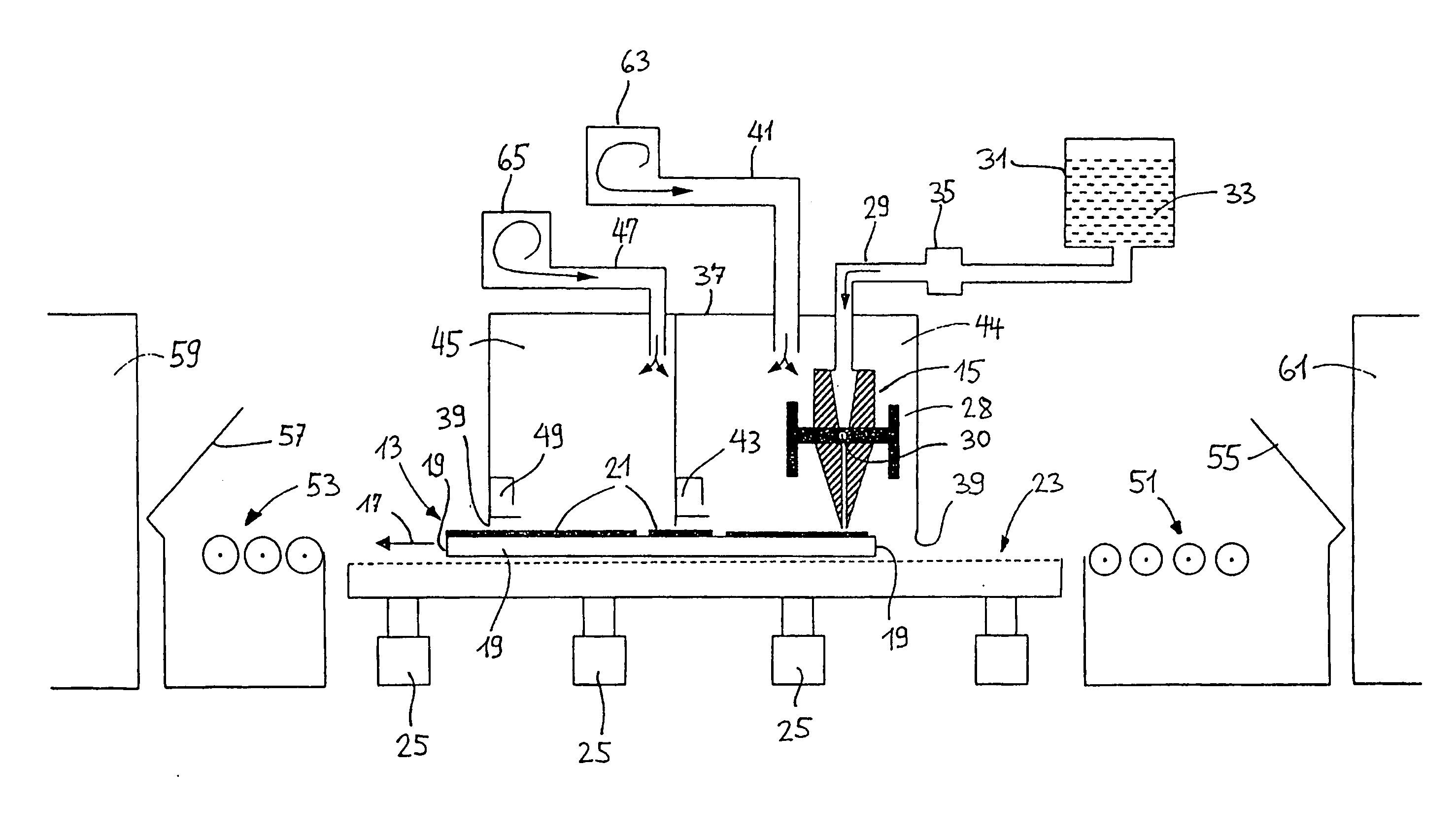
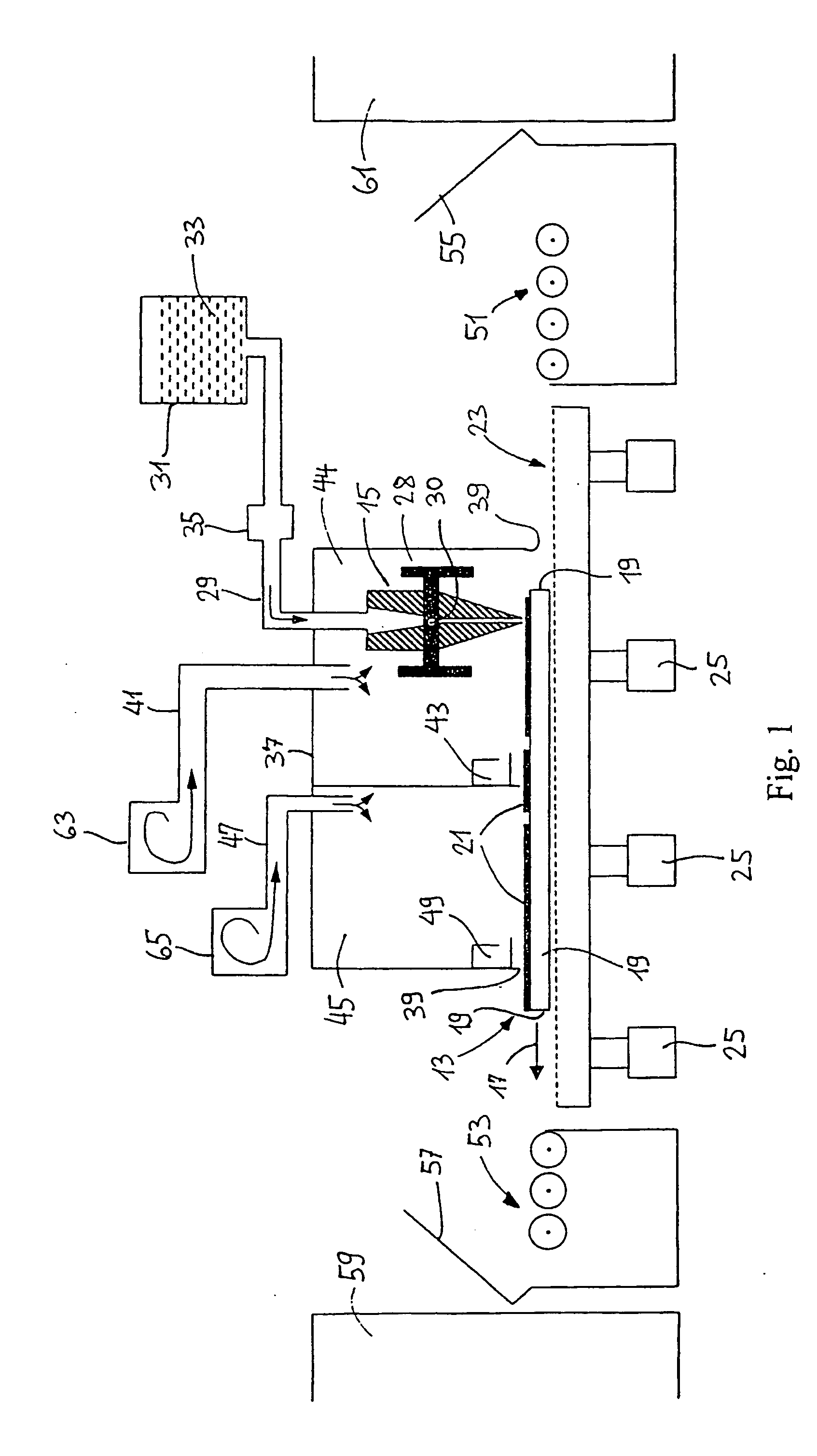
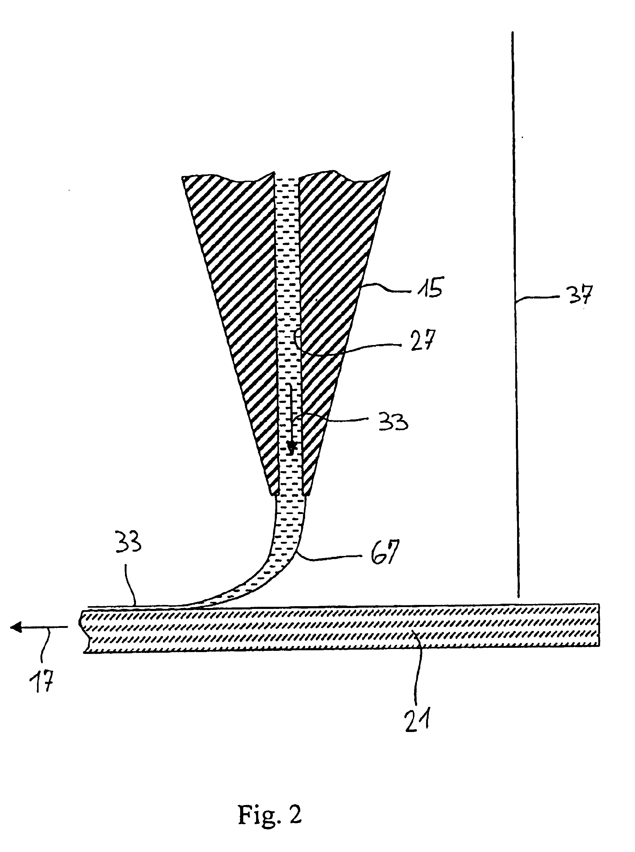
[0046] Object of the present invention is a device in accordance with claim 37, which is characterized in that the coating implement is a wide slot extrusion pourer with a slit-shaped outlet opening and that there is provided a device for circumcirculating the wide slot extrusion pourer with a process gas atmosphere at least in the region of the exit opening. This device could be a hood, or also a chamber that is substantially closed against the surrounding atmosphere, under which the wide slot extrusion pourer is arranged. The coating can thus be carried out in a defined process atmosphere. Advantageously, there will be provided at least one gas preparation plant that communicates with the chamber and makes available and / or mixes inert and / or reactive gas components. This makes it possible to utilize different gas atmospheres. The chamber may be provided with at least two connections for feeding and removing a process gas or process gas mixture. The chamber, in which the wide slot extrusion pourer is arranged, may be subdivided into at least two reaction spaces. Gas guidance devices may also be provided, for example guide sheets or lines with guide sheets, so that the gases can be purposefully directed towards the substrate surface or sucked away therefrom. Further advantageous embodiments of the coating plant are defined in the dependent claims.

Problems solved by technology

But these vacuum coating procedures are associated with considerable costs.
The coating procedures employed at present and the coating materials or chemical elements that can be used with them do not permit the coating of large areas of glass, especially plate glass, on one or both sides in a spectral bandwidth between about 350 nm and about 2000 nm.
The production costs of plate glass coated with the known methods would also be too high.
It is known that, for technological and particularly cost reasons, this coating cannot be used for large-area glass coatings.
But vacuum coating technologies are very cos-intensive procedures.
Given the poor rhibological properties and also the insufficient stabilities, however, the coated surfaces, prior to being subjected to, for example, mechanical loads, abrasive influences and / or environmental influences, have to be incorporated in a structure that protects them by constructive measures.
It is a disadvantage of both procedures that the production of antireflection layers is possible only as single layers.
The aforementioned three procedures call for very costly individual technical steps that are not technologically suitable for a continuous coating of plate glass or large-area plane substrates.
Since in each case at least one polymer is a layer-forming component of the nanoporous layer, it is not possible to harden the plate glass after the coating.
The procedure of WO 00 / 00854 cannot therefore be technically and technologically adapted for continuous coating of large-area plate glass with layer thicknesses in the nanometre range.
But these methods are not very suitable for an economic coating of large areas of glass substrates on an industrial scale.

Method used


Image

  • Method and device for the production of an antireflective coating, antireflective coating, and antireflective-coated substrate
  • Method and device for the production of an antireflective coating, antireflective coating, and antireflective-coated substrate
  • Method and device for the production of an antireflective coating, antireflective coating, and antireflective-coated substrate

Examples


1st example

1st Example

[0075] Production of a glass plate coated on one side with an anti-reflection layer to increase the total solar transmission.

[0076] In a suitable sequence and mixture, a silane producing fourfold cross-linking, a polymethyl acrylate with a molecular weight of 996,000, sulphuric acid and water are dissolved in a solvent that is effective for all substances and has a high vapour pressure at room temperature, setting an appropriate ratio between the two macromolecular materials and forcibly mixing the solution. The solid component of the coating solution amounts to a total of 5%.

[0077] The following values of the rheological properties were measured:

[0078] Viscosity=0.60 mPas,

[0079] Normal tension=8.5 Pa

[0080] The coating speed amounts to 7.0 m / min. The thickness of the solid material amounts to about 330 nm. By means of a high-temperature shock treatment in the glass hardening process, an average increase of the total solar transmission—as compared with uncoated plate ...

2nd example

2nd Example

[0081] Production as in Example 1 but with a solids content reduced by 50%. As compared with Example 1, the solids content of the coating solution amounts to only 2.3%. The share of polymethyl acrylate was reduced to a third as compared with Example 1. The addition of sulphuric acid and water was diminished in proportion to the reduction of the silane:

[0082] The following values of the rheological properties of the coating solution were measured:

[0083] Viscosity=0.43 mPas,

[0084] Normal tension=2.8 Pa

[0085] The coating speed amounts to 7.0 m / min. The thickness of the solid material amounts to 240 nm.

[0086] By means of the high-temperature shock treatment in the glass hardening process, an average increase of the total solar transmission—as compared with uncoated plate glass—of 1.8% (measured with the Ulbricht sphere) is obtained in the spectral range from 450 to 1500 nm. The anti-reflection layer was strikingly uneven to the naked eye.

[0087] As compared with Example ...

3rd example

3rd Example

[0088] Production of glass plates with single- or multiple layer coatings on one and / or both sides.

[0089] When producing multiple coatings on glass plates, the simply coated glass plates or other substrates are either fed back by means of a technological by-pass or coated with the help of a second wide slot pourer. After leaving the coating chamber, the applied solids layer is mechanically so stable as to permit substrates coated on one side to be moved even on the coated side by means of the automated transport customary in the glass processing industry. As far as processing possibilities are concerned, prior to the glass hardening process one may therefore choose either to coat the rear side of the substrate with the same coating solution and the same coating conditions, or to coat the substrates once again on either one or two sides to obtain a double coating.

[0090] Changing the substrate speed and / or the flow quantities, it becomes possible to modify the layer thick...


PUM

PropertyMeasurementUnit
Fractionaaaaaaaaaa
Fractionaaaaaaaaaa
Fractionaaaaaaaaaa

Abstract

In order to produce an antireflective layer, a coating solution containing at least one metal alkoxy compound and at least one polymer as solid components that are dissolved in a solvent is applied to a substrate that is to be coated by means of a pouring device with a wide slit, the polymer being immiscible and essentially inert in a chemical manner towards the metal alkoxy compound. A layer which is provided with a nanoporous structure having a refractive index that is preferably smaller than 1.22 as well as good antireflective properties is obtained by selective removal of the polymer and thermochemical hardening of the coating.

Description

[0001] The present invention relates to a procedure and a plant for the production of a porous antireflection coating on a transparent substrates, such as glass panes made of plate glass or cast glass, an antireflection coating and an antireflection-coated substrate. [0002] The use of hardened plate glass in solar technology makes it desirable to increase the transmission not only within narrow spectral ranges, but also integrally over the entire spectral range of solar transmission, preferably over a spectral range from about 350 to about 2000 nm. Hardened plate glass dereflected on one side is preferably needed in phovoltaics. Solar heat production, at least with the design principle employed by the greater part of producers, calls for hardened plate glass dereflected on both sides. [0003] It is known that antireflection layers can be applied to plate glass and other light-permeable substrates by means of vacuum coating techniques. But these vacuum coating procedures are associate...

Claims


Application Information

Patent Timeline
IPC IPC(8): B05D1/26B05D3/02F24J2/48B05D3/04B05D3/06B05D7/04B05D7/14C03C17/00C03C17/25C03C17/28C03C17/30G02B1/11
CPCB05D1/265B05D3/0263B05D3/046B05D3/0466B05D3/067B05D7/04G02B1/11C03C17/002C03C17/006C03C17/25C03C2217/213C03C2217/425C03C2218/113B05D7/14F24S80/52F24S80/56Y02E10/40
Inventor WALHEIM, STEFANSTEPS, JURGENHOLZBECHER, MARTIN
Owner INTERFLOAT CORP
Learn More