Down hole air diverter

a diverter and air technology, applied in the direction of borehole/well accessories, drilling pipes, drilling rods, etc., can solve the problems of inability to fully adapt, inability to fully appreciate, and inability to drill mud, so as to reduce the type of situation, reduce the environmental impact, and save costs.

Inactive Publication Date: 2005-11-10
MELLOTT JOSEPH C
View PDF17 Cites 18 Cited by
  • Summary
  • Abstract
  • Description
  • Claims
  • Application Information

AI Technical Summary

Benefits of technology

[0028] A primary environmental advantage of the present invention is the reduction in types of situations where oil based mud may be required to accomplish drilling to the target objective. By increasing the number of situations where the drilling may be completed without resort to switching from pneumatic fluid drilling to liquid or oil based mud drilling, significant reduction in environmental impact and cost savings may be obtained.
[0029] Another advantage which is also related to environmental impact is the reduction in total energy usage required to drill a well. Through the use of the computer modeling or the valve of the present invention, either each alone or both in combination using the described method of operation, a reduction in required pneumatic fluid pressure is achieved. Reduced pressure requirements lead to reduced horsepower needs for generating pressure, which ultimately leads to overall energy usage savings. To date, tests show an actual energy savings of at least 15%, although higher percentage savings are anticipated as experience is obtained in practicing the present invention.
[0030] An object of the present invention is to reduce the washout of soft formations caused by wasted friction energy put into the annulus at the bit.
[0031] A further object of the present invention is to reduce the bottom hole pressure, thereby achieving better energy coupling at the bit and optimizing the rate of penetration.
[0032] Another object of the present invention is to reduce unwanted hole deviation while using a hammer tool and flat bottom bit. This is accomplished by reducing the weight necessary to fully close the hammer tool, thereby reducing the tendency for the hammer tool to drift.
[0033] Another advantage of the present invention is that no additional pneumatic fluid is needed to clean the hole.

Problems solved by technology

Drilling mud, however, is relatively incompressible when compared to the compressible gases of a pneumatic fluid.
Many drillers in the field either do not fully appreciate these differences, or are not fully able to adapt to these differences in their drilling procedures.
The complexity, and the incorrect application of drilling-mud techniques to pneumatic drilling, has generally prevented the industry from taking advantage of this additional level of control provided by pneumatic drilling.
One of the problems of drilling with pneumatic fluid is that all of the pneumatic fluid flows down the drill string, through the drill bit, and up the well bore.
Frictional losses are significant.
Also, there is no control of the velocity of the pneumatic fluid along the well bore, as changes in the well bore volume will directly affect the compression of the pneumatic fluid.
Second, excess pneumatic fluid flow at the bit can cause excessive erosion of the well bore.
Unfortunately, many of these promised advantages met with limited success, owing to limitations of the diverters and their method of application.
Without a computer model to augment the diverter tool, it was impractical to select the optimum volume of air to divert, locate where to place the diverter tool, select what nozzle size to use for the valves, and estimate savings from the reduced down hole friction.
The complexities of modeling a compressible pneumatic drilling fluid over a relatively incompressible drilling-mud limited the usefulness of diverter technology.
Previously, this was not possible without a diverter.
Hence, little energy savings was realized.
Hence, these diverter valves typically fluttered, causing an unpredictable and erratic amount of diversion.
The diverter tool could not be used to selectively control the lift gradient in the well bore, due to its normally closed position and inability to be independently opened by the drill pipe pressure alone.

Method used


Image

  • Down hole air diverter
  • Down hole air diverter
  • Down hole air diverter

Examples


Embodiment Construction

[0222] Down Hole Air Diverter

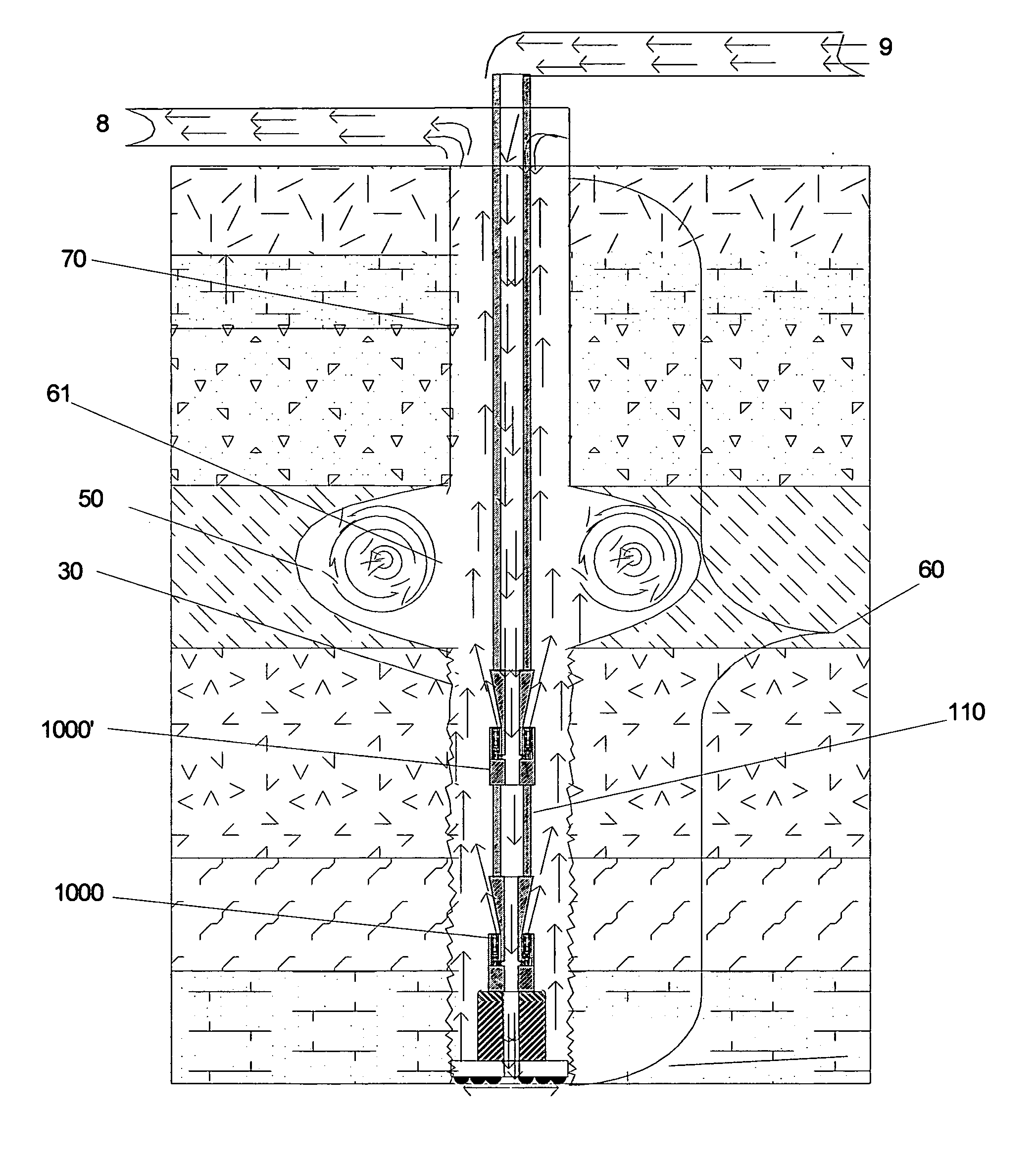
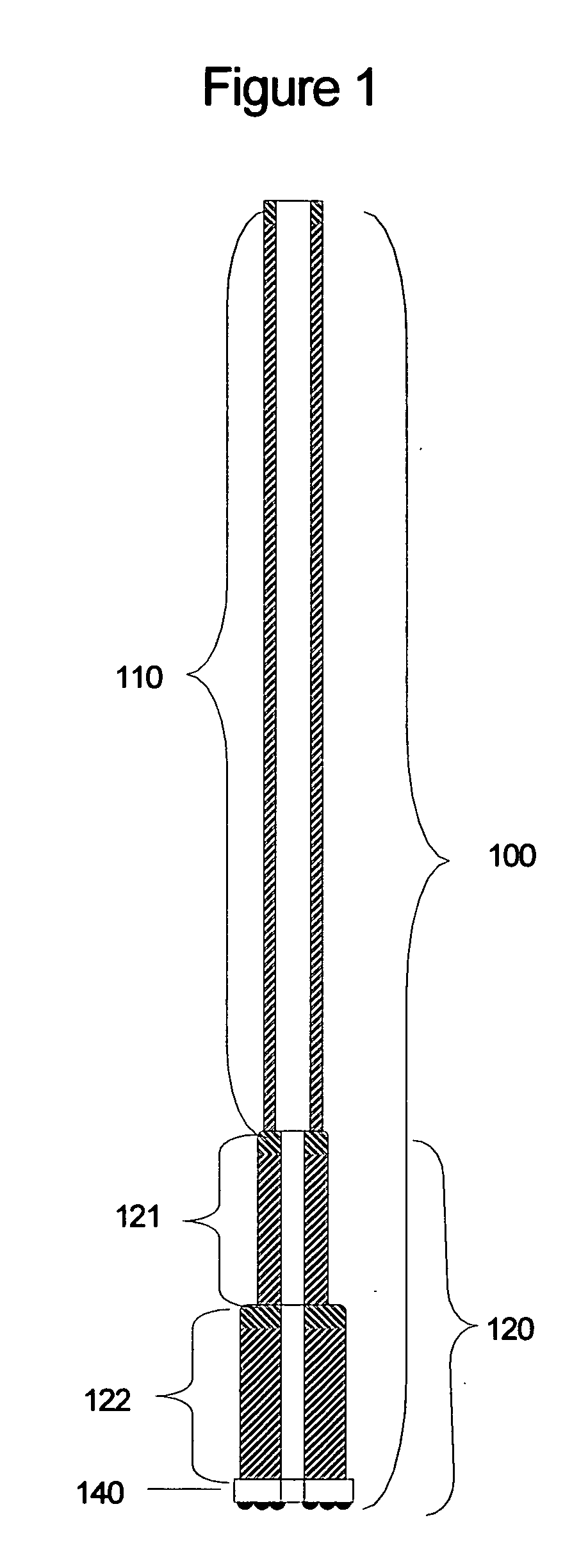
[0223] A typical drilling configuration is shown in FIG. 1. Drillstring combination 100 comprises a plurality of drillpipe 110 attached end to end, having a passageway along its axis, and connected to a bottom hole assembly 120. In practice, any of a wide variety of components may comprise drillstring combination 100. Bottom hole assembly 120 comprises a plurality of drill collars 121, which typically have an outside diameter greater than drillpipe 110, and optionally a plurality of drill collars 122 of larger outside diameter, and drill bit 140. The passageway of drillpipe 100 typically has a diameter greater than the passageway of drill collars 121 and drill collars 122. The flow area created by the diameters of the passageway of drill collar 121 is typically at least three times smaller than the flow area created by the diameter of the passageway of drillpipe 110. Therefore there is typically a significant amount of available pneumatic fluid energy a...


PUM


Abstract

The present invention provides an improved method of and apparatus for, pneumatic drilling. The present invention includes a down hole air diverter of improved design, a corresponding computer modeling program, and method of application to optimally achieve the benefits of controlled gradient pneumatic drilling.

Description

REFERENCE [0001] Pursuant to 35 U.S.C. 119(e)(1), reference is hereby made to earlier filed provisional Patent Application No. 60 / 569,317 to Joseph C. Mellott for Down Hole Air Diverter of filing date May 8, 2004. This application claims the benefit of U.S. Provisional Application No. 60 / 569,317, filed May 8, 2004.FIELD OF THE INVENTION [0002] The present invention relates generally to drilling well bores into subsurface geologic strata. More specifically, it relates directly to the controlled use of a pneumatic fluid as the medium to transport energy to the well bore and bottom hole, and to remove drilled cuttings, injected liquids and liquids produced from these subsurface strata. BACKGROUND OF THE INVENTION [0003] Typically, a liquid called drilling mud is used to drill well bores. Under certain conditions, a pneumatic fluid, such as air, may be used instead of drilling mud to drill well bores. At first, drilling with a pneumatic fluid initially appears to be less complicated tha...

Claims


Application Information

Patent Timeline
Patent Type & Authority Applications(United States)
IPC IPC(8): E21B21/00E21B21/16
CPCE21B21/16
Inventor MELLOTT, JOSEPH C.
Owner MELLOTT JOSEPH C
Why Eureka
Try Eureka