Method and device for fabricating plastic molded article
Inactive Publication Date: 2005-11-24
RICOH KK
View PDF1 Cites 6 Cited by
Summary
Abstract
Description
Claims
Application Information
AI Technical Summary
This helps you quickly interpret patents by identifying the three key elements:
Problems solved by technology
Method used
Benefits of technology
Benefits of technology
[0021] A specific object of the present invention is to provide a method and a device able to ease fabrication of a plastic molded article having a minute shape, and the plastic molded article.
[0057] According to the present invention, it is possible to easily fabricate a plastic molded article having a minute shape.
Problems solved by technology
As illustrated inFIG. 22A through FIG. 22G, lithography is performed by using synchrotronradiation of high directionality, resulting in a high-aspect-ratio molded article having unevenness.
However, as for the above-described method (1), namely, injection molding, although productivity of the method is excellent, this method is not suitable for experimental production; hence, it is difficult to use this method to form minute shapes.
Concerning the above-described method (2), namely, photolithography, this method requires expensive production equipment, while only being capable of fabricating molded articles not thicker than a few tens μm.
Further, this method requires waste disposal accompanying development treatment.
As for the above-described method (3), namely, the LIGA process, the synchrotronradiation equipment is quite expensive, even though the mold is ordered from an outside supplier, the cost is still very high.
Concerning the above-described method (4), namely, the rapid prototyping process, this method is quite effective for produce a complicated three dimensional minute shape, but it is quite time-consuming even when fabricating a single article; especially, productivity of this method is quite poor when fabricating an article of a single shape and large area.
Method used
Image
Click on the blue label to locate the original text in one second.
Reading with bidirectional positioning of images and text.
[0102] In this example, an ultraviolet curable resin was added into a fluorine-based oil by an amount of 2% in weight (or in mass), and was agitated by a rotational blade type stirrer with a long axis of 17 mm at 600 rpm for six minutes.
[0103] Here, the ultraviolet curable resin acts as a dispersed solute, which is a low dielectric constant liquid or a high dielectric constant liquid in a dispersed solution. The fluorine-based oil acts as a dispersed solvent, which is the high dielectric constant liquid or the low dielectric constant liquid in the dispersed solution.
[0104] In this example, an ultraviolet curable resin manufactured by Henkel Japan Ltd. (product name: Loctite 3311) was used, and a fluorine-based oil manufactured by Daikin Industries Ltd. (product name: S-65) was used.
[0105] As a result, the ultraviolet curable resin was dispersed into droplets of about 10 μm in diameter, and a dispersed solution (a liquid mixture) was ...
[0120] The processing in the present example is basically the same as that in the example 1 except that a direct-current electric field of 1.0 V / μm was applied in the present example. A plastic molded article substantially the same as that in the example 1 was obtained.
[0121] In this example, a silicon oil manufactured by Sin-Etsu Chemical Co. Ltd. (product name: Sin-Etsu silicone KF-96-500CS) was used, and an alternating-current electric field of 1.0 V / μm (an alternating voltage of 50 Hz and 1.5 kV) is applied between the copper electrodes 3, 4. The other processing in the present example is the same as that in the example 1, and the bridge structure 11 shown in FIG. 8 was obtained.
[0122]FIG. 8 is a view of the bridge structure 11 obtained in the present example.
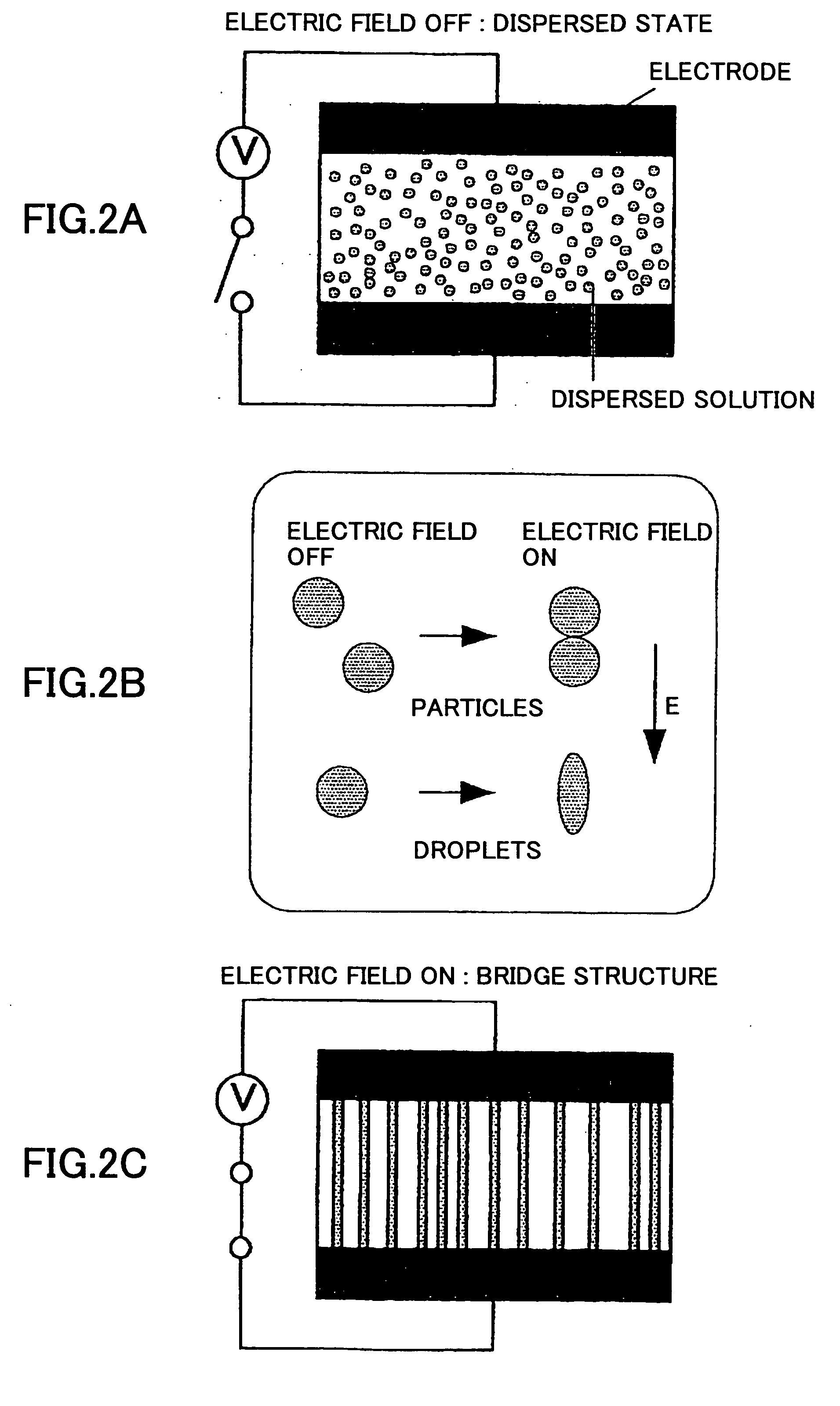
[0123] In this example, upon application of the electrical field, due to polarization of the droplets of the ultraviolet curable resin, these droplets aggregate caused by a Coulomb attractive force, and as a result, the diameter of each bridge10 is about 300 μm, much greater than that in example 1.
[0124] After irradiation of ultraviolet rays onto the bridge structure 11 and curing of the curable resin, the bridge structure 11 was fixed, which inc...
PUM
Property
Measurement
Unit
Concentration
aaaaa
aaaaa
Structure
aaaaa
aaaaa
Dielectric constant
aaaaa
aaaaa
Abstract
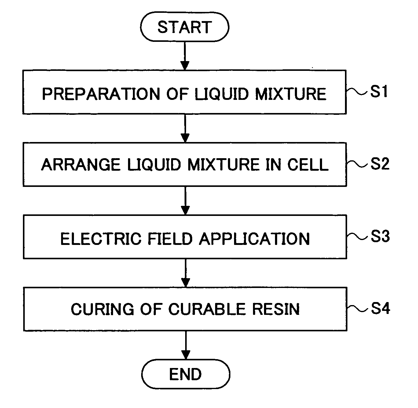
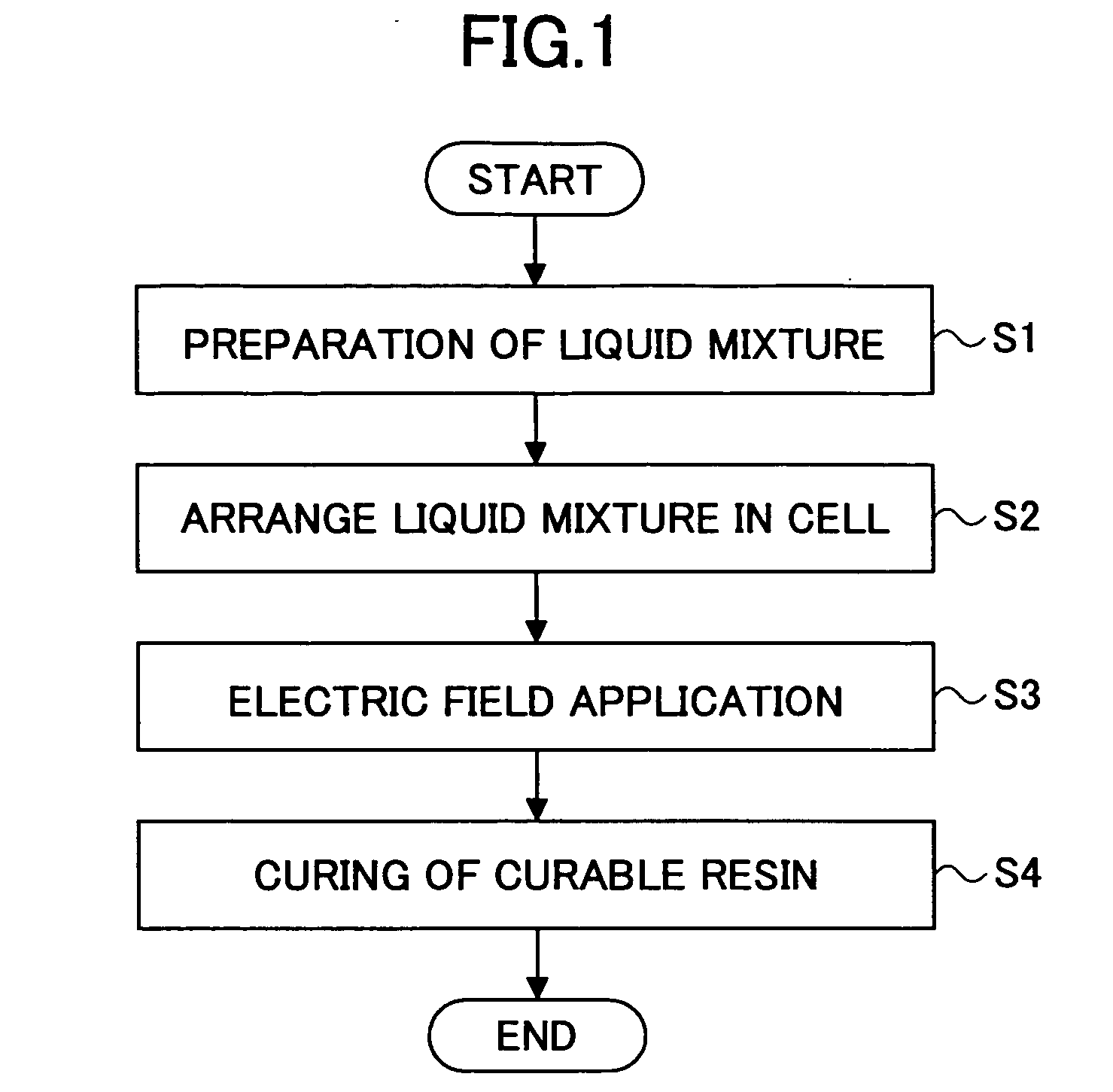
A method of fabricating a plastic molded article is disclosed. In the method, a compound liquid, including two component liquids insoluble in each other and having different dielectric constants, is supplied between two electrodes, and an electric field is applied between the electrodes. At least one of the component liquids is an un-cured curable resin liquid. Upon application of the electric field, the higher dielectricconstant component liquid is extended along the direction of the electric field, thus forming a bridge structure linking the electrodes. When the curable resin is cured after the bridge structure is formed, a plastic molded article is obtained.
Description
BACKGROUND OF THE INVENTION [0001] 1. Field of the Invention [0002] The present invention relates to a technique of fabricating a plastic molded article applicable to fabrication of a minute or small structure in the order of μm to nanometers. [0003] 2. Description of the Related Art [0004] In the related art, the following techniques are well known for fabricating a plastic molded article (synthesized resin product). [0005] (1) Injection Molding [0006] Specifically, after filling a mold with a melted resin, the melted resin is cooled to obtain a plastic molded article. For example, reference can be made to Japanese Laid Open Patent Application No. 5-185464. [0007] (2) Photolithography [0008]FIG. 21A through FIG. 21C are cross-sectional views schematically illustrating a method of fabricating a plastic molded article by photolithography. [0009] As illustrated in FIG. 21A through FIG. 21C, a thin film formed from a synthesized resin on the surface of a substrate is partially removed ...
Claims
Application Information
Patent Timeline
Application Date:The date an application was filed.
Publication Date:The date a patent or application was officially published.
First Publication Date:The earliest publication date of a patent with the same application number.
Issue Date:Publication date of the patent grant document.
PCT Entry Date:The Entry date of PCT National Phase.
Estimated Expiry Date:The statutory expiry date of a patent right according to the Patent Law, and it is the longest term of protection that the patent right can achieve without the termination of the patent right due to other reasons(Term extension factor has been taken into account ).
Invalid Date:Actual expiry date is based on effective date or publication date of legal transaction data of invalid patent.

