The standard Papanicolaou wet fixed smear has the very significant problem of inadequate sampling of the material scraped from the
cervix.
This has the significant problem that cells can fall off of a receiving surface member, such as a
microscope slide, and even worse be transferred and adhere to a different receiving surface member.
If these diagnostic cells instead of being lost from a first slide adventitiously attach to a second slide, then a false diagnosis of
malignancy can occur.
Thereafter, the slide could be manually removed or transferred by some automated means “implemented by known devices in the art.” (Col. 3, lines 50-51) The combination of standard or specialized
robotics to transfer the
microscope slide and the automated
staining machine can be can be complex and is expensive in labor,
capital cost, and bench space.
The CYTYC
system has the problem of selective loss of cells and other diagnostic materials.
The systems described in the above patents are complex, involve significant numbers of
moving parts including belts, and require a complex disposable, the sample collector, which includes an expensive filter.
These systems only produce one
cell dispersion at a time, are expensive; because their mechanical complexity results in significant maintenance costs; and requires ancillary expensive equipment, such as a slide stainer.
The dispersions of the slides produced have selected loss of particles smaller than the pore size of the filters; and the possibility of
selective transfer of different types of cells from the filter to the slide can not be totally eliminated.
This procedure required significant manual labor, could not be directly automated, would require a complex
mechanical system to invert the buckets, did not provide a complete solution to the problem of cross-
contamination because the same
pipette was used to add the solvents to the buckets, and provided minimal safety against the biohazards associated with human samples.
This
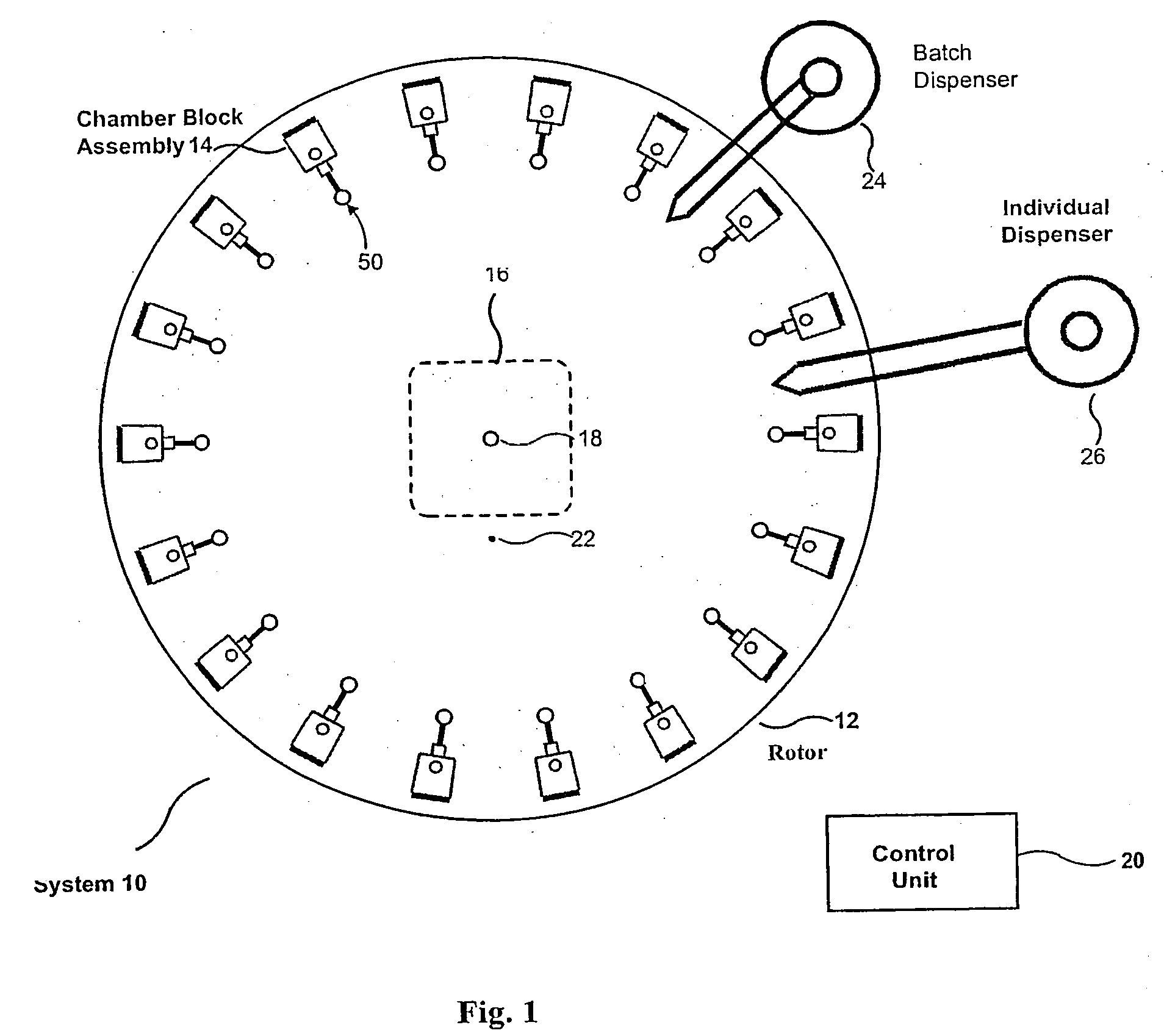
system has the following limitations: 1) The sample chambers are part of the rotor.
Since the chambers are part of the rotor, they cannot be premanufactured to be both clean (
cell free) and attached to the slide.
2) Each chamber requires its own electronically controlled valve, which requires transfer of a significant amount of
electricity to the rotor.
3) Because the valves have to repeatedly retard the fluid under full load, they can be caused to leak out the
cell containing fluid by the presence of an imperfection or debris.
6) The rotor can not be removed easily from the
centrifuge for cleaning and maintenance.
This problem is exacerbated by the necessity of stabilizing samples for shipment from the place where they were acquired to the clinical laboratory where they are prepared and analyzed.
This design “permits individual collection and segregation of supernatant withdrawn from the vicinity of the deposition surface.”(Col. 8, lines 45-47) The use of a vacuum
system significantly increases the cost and complexity of the device, as well as decreases its reliability.
It also significantly increases the probability of air-
drying of the cells, which causes a significant decrease in the quality of their morphology.
This type of seal increases the cost and complexity of the device, as well as decreasing its reliability.
In this instance, the exhausted fluid will atomize or “
aerosol” within the housing (not shown) for the rotor.” (Col. 5, lines 31-35) This would present an unacceptable
biohazard.
(Col. 5, lines 37-44) This design will wash the chamber; however, it will not stop the premature loss of cell containing supernatant.
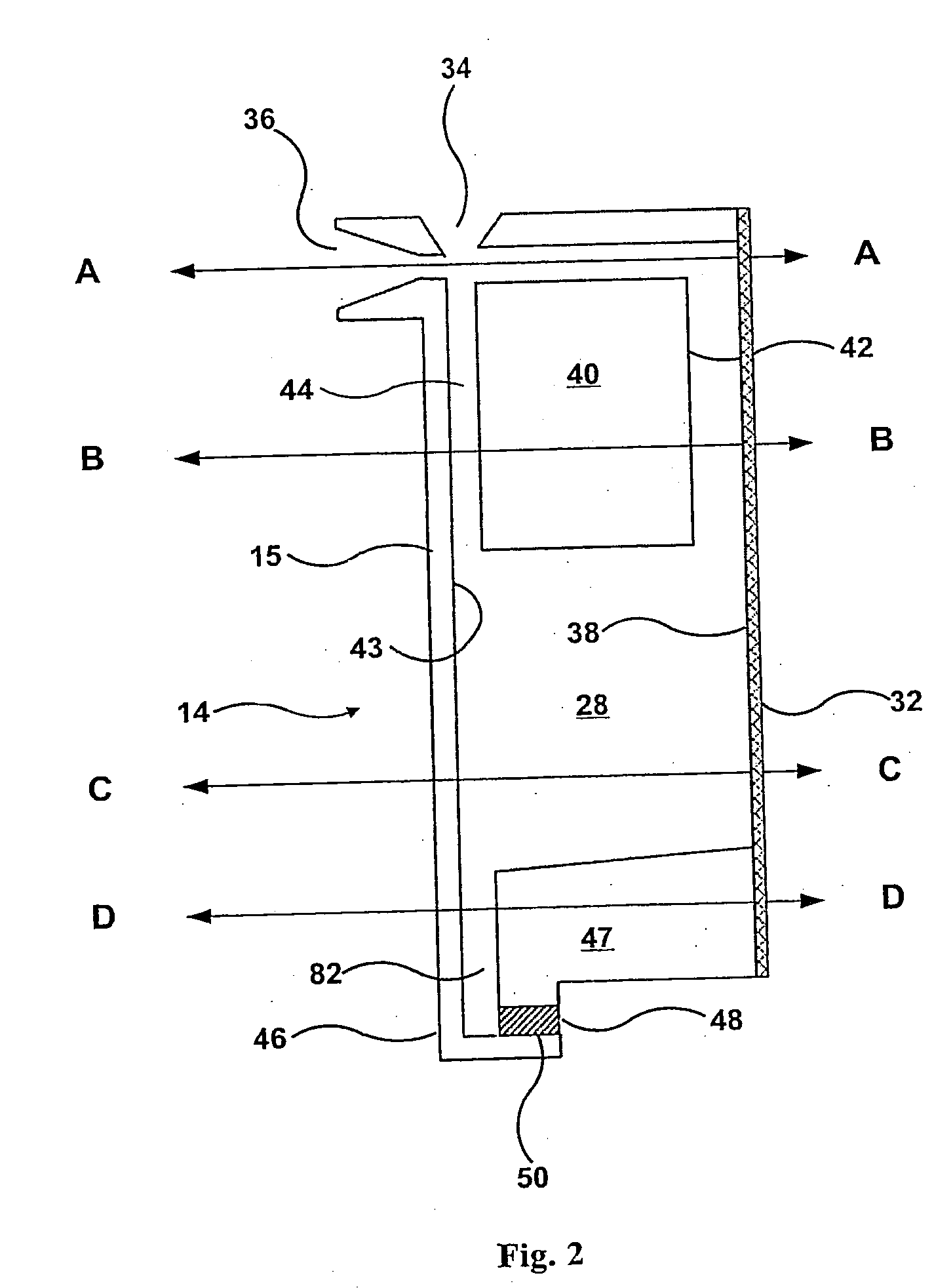
However, the design shown in FIG. 1 limits the volume of sample, so that it is not suitable for cervical-vaginal and other cell suspensions of clinical interest.
Mechanical dissociation of these cells also requires a significant volume of fluid.
The two arms of the U tube will be brought into balance by the
centrifugal field with the result that significant cell containing fluid could be lost or the volume of sample would be small and insufficient for many cytological preparations, such as cervical
cytology preparations.
“In practice, however, it has been found that while the
centrifuge rotor rotates to its
operating speed the presence of the absorbant
plug in next adjacency to the deposition surface has the effect of prematurely withdrawing both supernatant and cells suspended therein.
This is perceived as disadvantageous since it prevents the
sedimentation of cells on the surface.” (Col. 1, lines 43-49)
These plugs and housings are both complex and would require special instruments to remove them for the required cleaning, prior to reuse of the chamber blocks.
The protruding of the
trailing edge of the
solid plug U.S. Pat. No. 4,574,729 (Ref. 41) can interfere with the removal of the chamber blocks from the rotor.
If the fixative floats, its
efficacy will be greatly diminished.
If it sinks, the cells will be partially fixed as they
traverse the fixative and proteins and other matter in the sample will be precipitated by the fixative and contaminate the surface of the slide.
This decrease in
cell concentration and limited deposition area of this cytocentrifugation device can result in a significantly reduced number of diagnostic cells, which renders the sample inadequate or suboptimal for diagnosis (Ref. 27).
Thus, this device is incapable of stopping the rotor and performing sequential additions of liquids.

