

Semiconductor device
a technology of semiconductor devices and semiconductors, applied in the direction of semiconductor devices, basic electric elements, electrical appliances, etc., can solve the problems of insufficient cut-off frequency fc, and the method cannot be applied to an avalanche photodiode with an alinas layer or an algaas layer as a multiplication layer, so as to achieve the effect of improving the frequency characteristi
- Summary
- Abstract
- Description
- Claims
- Application Information
AI Technical Summary
Benefits of technology
Problems solved by technology
Method used
Image

Examples
first embodiment
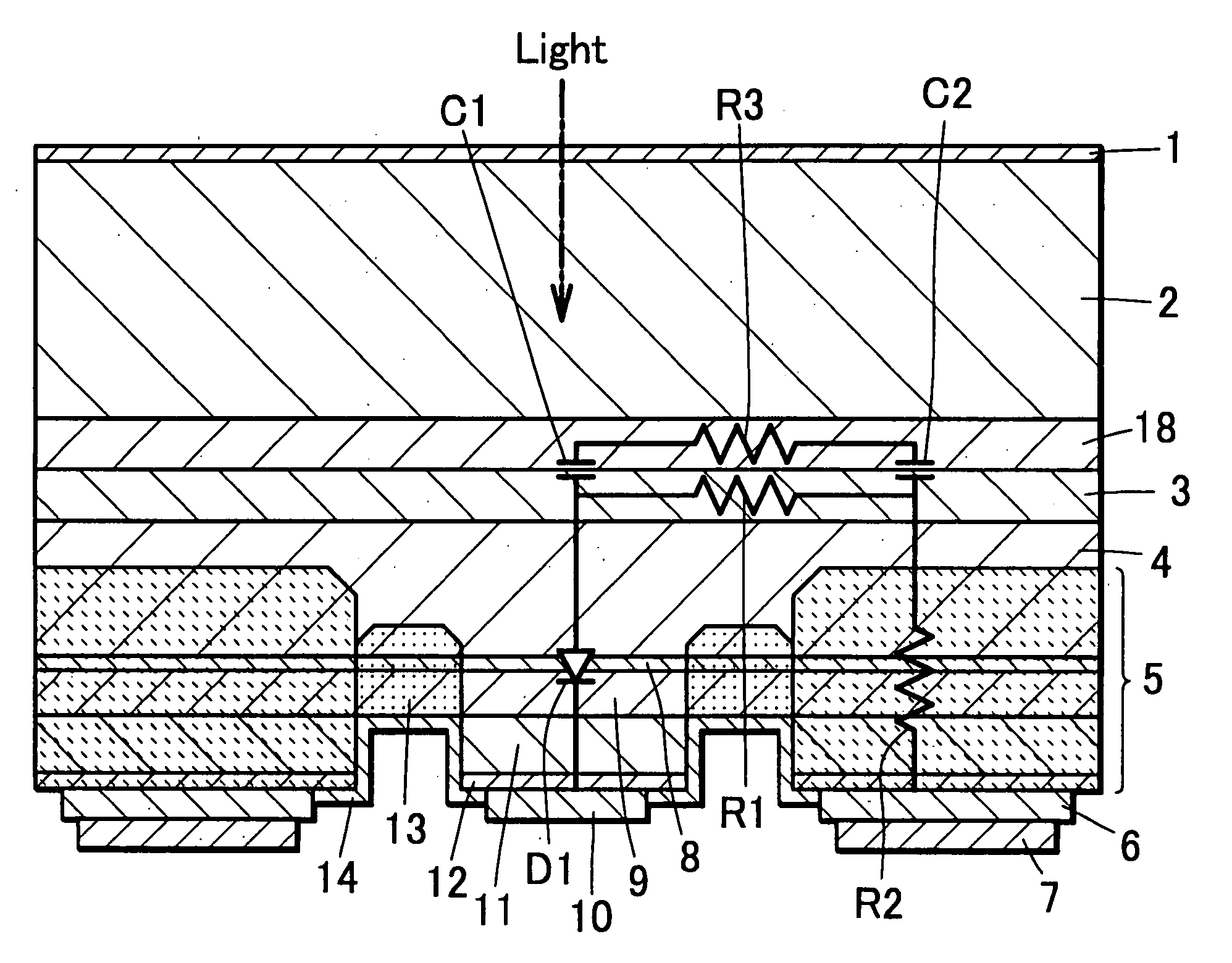
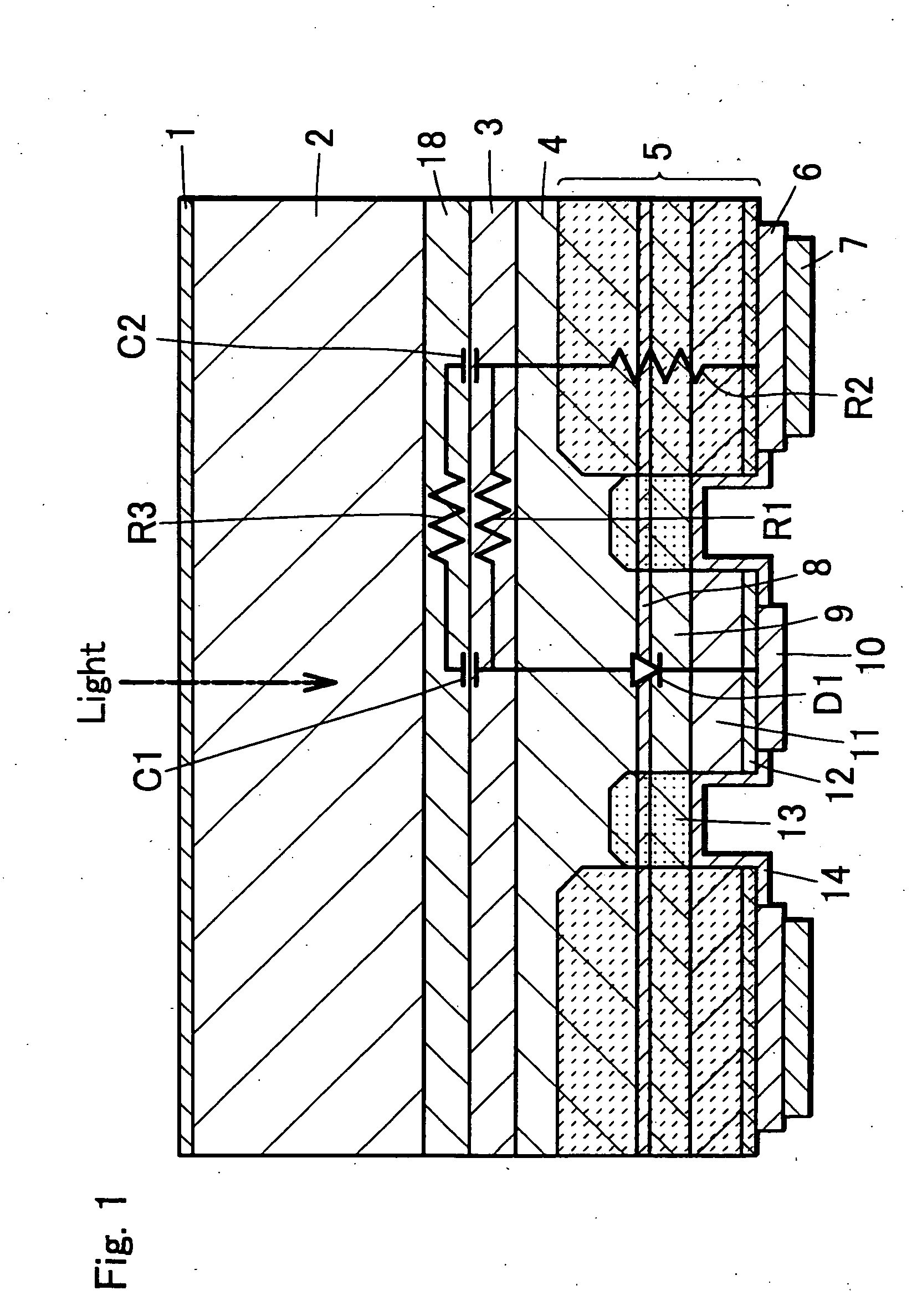
[0031] An optical semiconductor device of a first embodiment according to the present invention is an avalanche photodiode and the avalanche photodiode is constructed in a similar way to that in the conventional example avalanche photodiode of FIG. 10 with the exception that in the conventional example avalanche photodiode of FIG. 10, an n type layer 18 is formed between the semi-insulating InP substrate 2 and the p type layer 3 with a high carrier density.
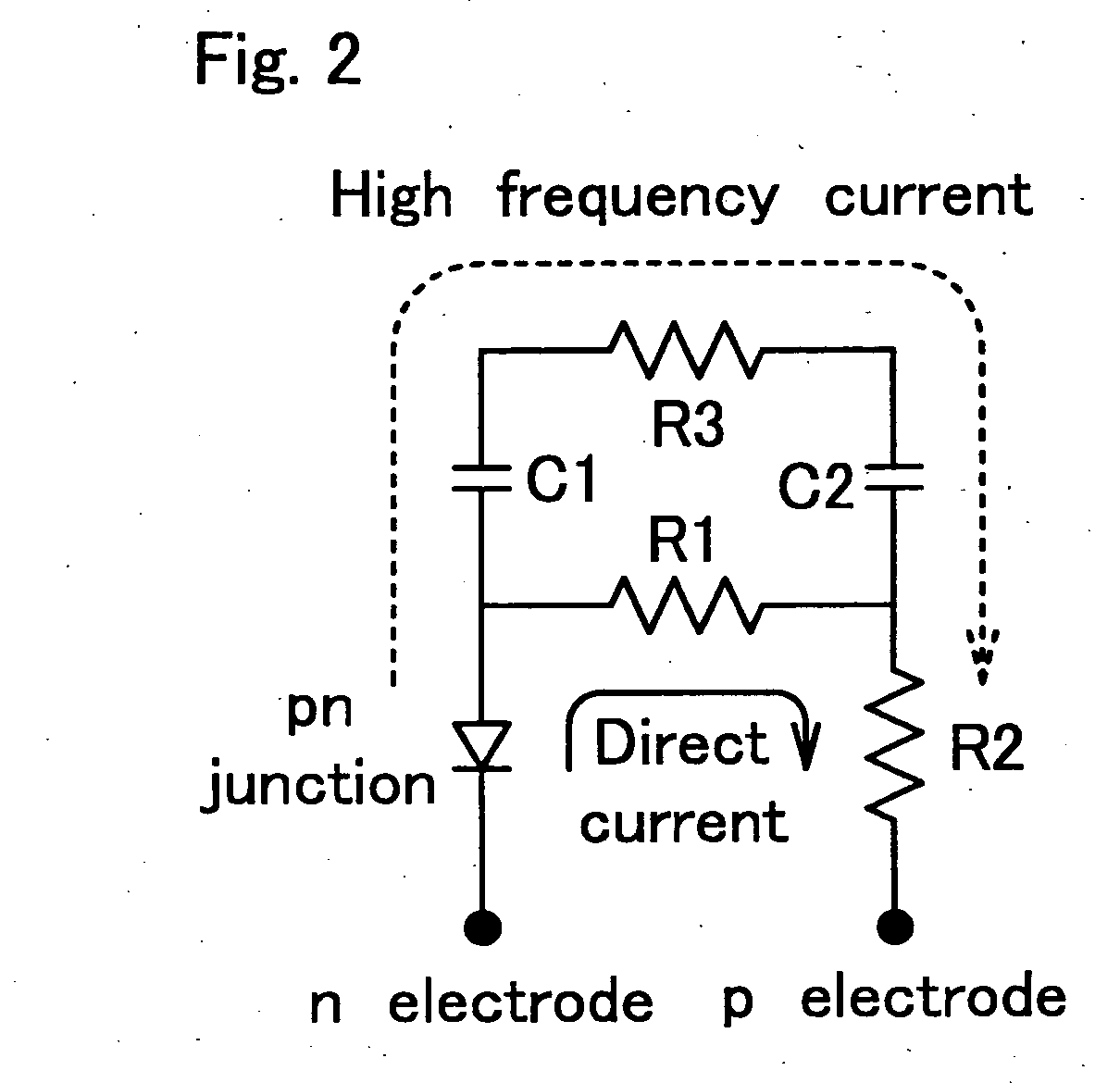
[0032] That is, an equivalent circuit of the avalanche photodiode of the first embodiment is such that in the equivalent circuit of a conventional example avalanche photodiode shown in FIG. 11, as shown in FIG. 2, a series circuit including a capacitance C1, a resistance R3 and a capacitance C2 is connected in parallel to a resistance R1. Herein, in the equivalent circuit of FIG. 2, the capacitance C1 is a pn junction capacitance generated between a p type layer 3 in a light receiving region and an n type layer 18, the resistance...
second embodiment
[0045] Then, description will be given of an avalanche photodiode of a second embodiment according to the present invention.
[0046] In the first embodiment, description is given of the case where the p type layer 3 and the n type layer 18 are made of InP, while in the second embodiment, description will be given of an example in which the p type layer 3 and the n type layer 18 are made of another compound semiconductor in an avalanche photodiode with a structure of FIG. 1.
[0047] To be detailed, in the present invention, as the p type layer 3 and the n type layer 18, for example, one selected from the group consisting InAlAs, InGaAsP, AlGaInAs and InGaAs may be used in one layer or in both layers. In a case where the substrate is made of GaAs, GaAs or AlGaAs may be used in one layer or both layers as a structural material.
[0048] In the present invention, to form both or one of the p type layer 3 and the n type layer 18 with a compound semiconductor with a bandgap almost less than 1...
third embodiment
[0053] An avalanche photodiode of a third embodiment is similar in fundamental compound semiconductor layer structure to that of the first embodiment with the exception that light comes in through the substrate 2 in the avalanche photodiode of the first embodiment, while in an avalanche photodiode in the third embodiment, light comes in from the side on which the n type side electrode is formed.
[0054] The detailed differences from the first embodiment are the following items. [0055] (1) A metal film 22 for device bonding is formed instead of the antireflection film 1 on the rear surface of the InP substrate 2. [0056] (2) An annular n type side electrode 10a having an opening for incident light to come in is formed in instead of the n type side electrode 10. [0057] (3) An antireflection film 1a is formed on the n type contact layer 12 in the opening of the n type side electrode 10a.
[0058] The avalanche photosensitive diode of the third embodiment is constructed in a similar way to ...
PUM
 Abstract
Description
Claims
Application Information