Radiation image pickup apparatus and its control method
- Summary
- Abstract
- Description
- Claims
- Application Information
AI Technical Summary
Benefits of technology
Problems solved by technology
Method used
Image
Examples
second embodiment
(Second Embodiment)
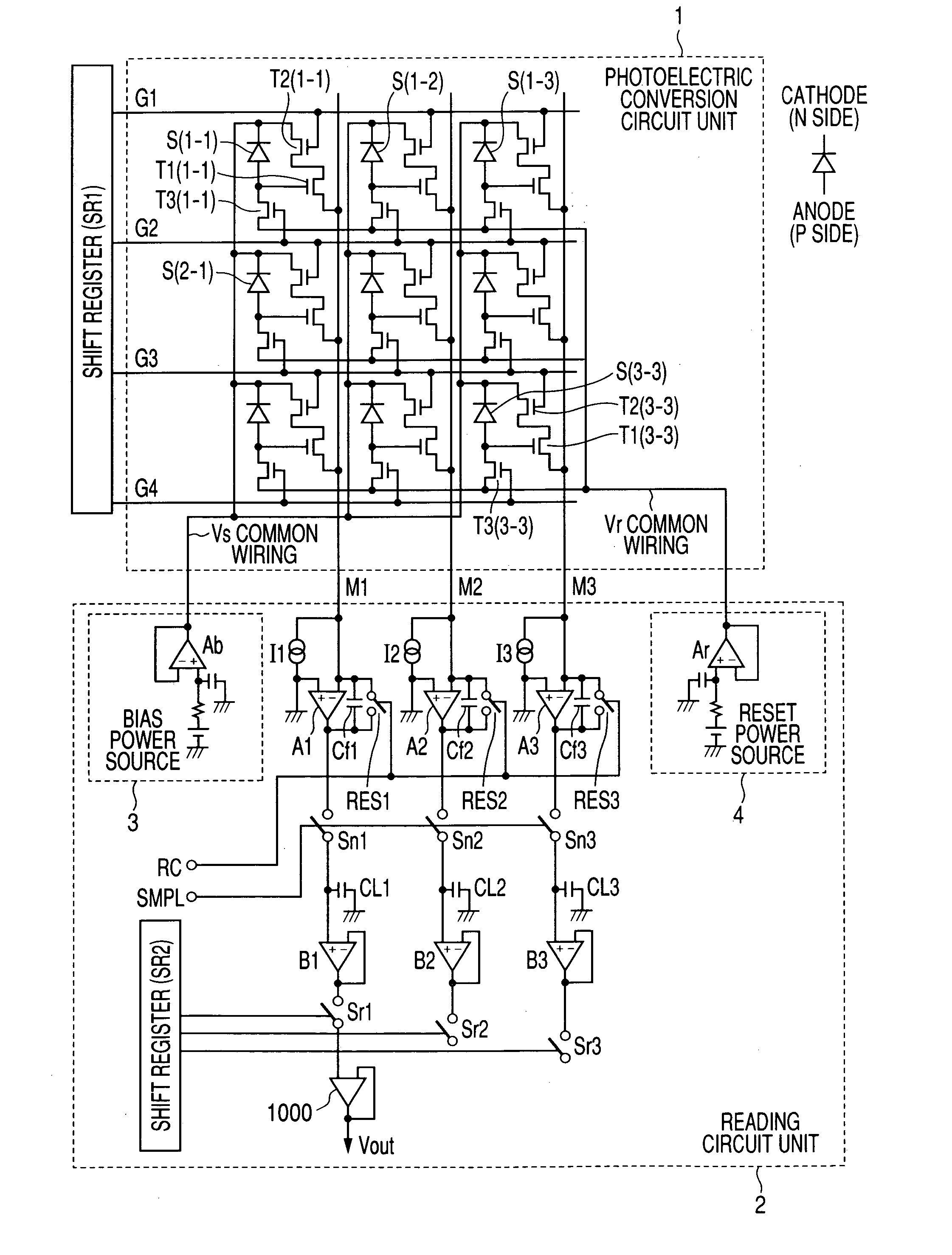
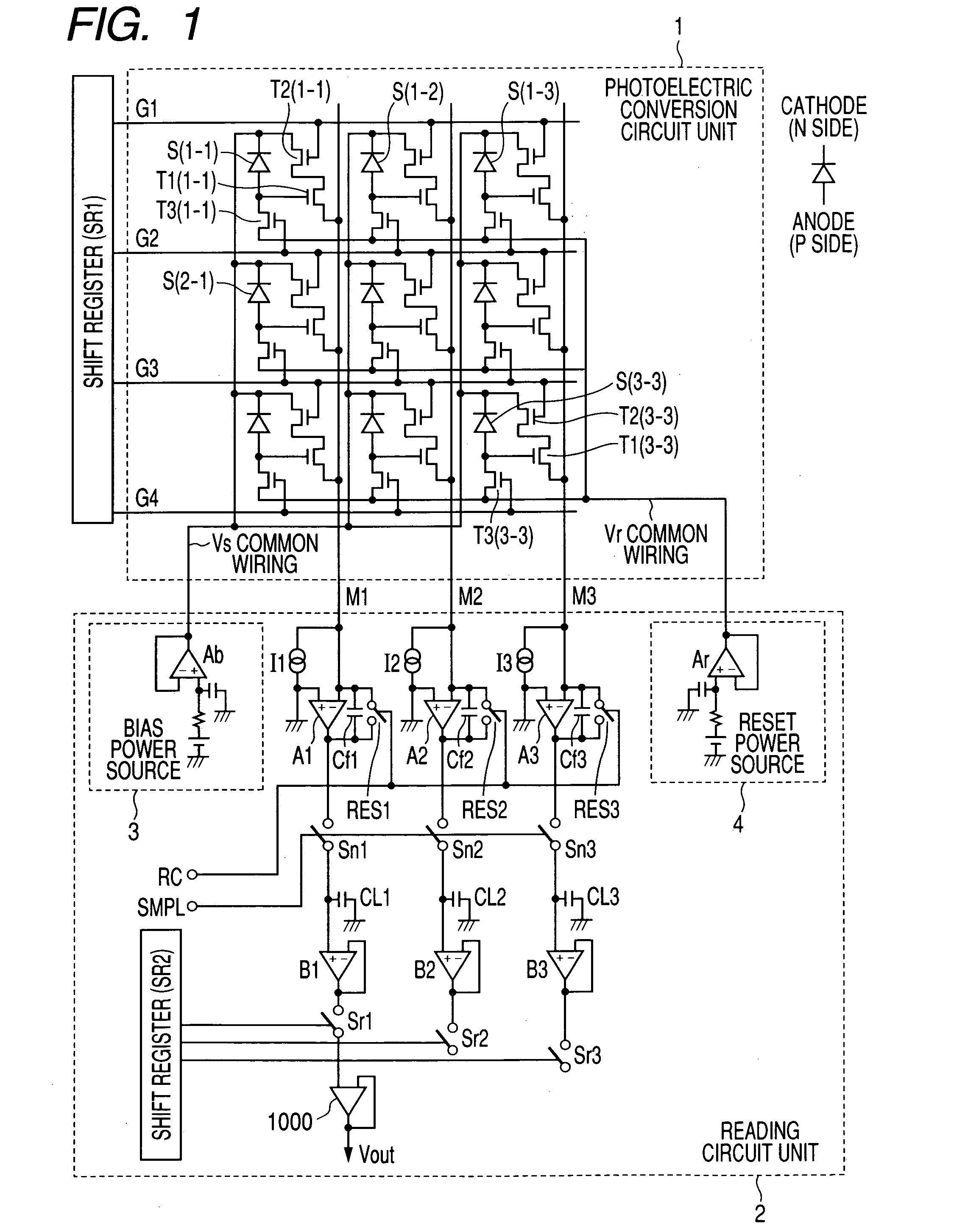
[0091] Then, second embodiment of the present invention is described below. FIG. 3 is an illustration showing a two-dimensional circuit configuration of the X-ray image pickup apparatus (radiation image pickup apparatus) according to the second embodiment of the present invention. FIG. 3, shows 9 pixels=3×3 pixels in order to simplify description.
[0092] In FIG. 3, S(1-1) to S(3-3) are photoelectric converting devices for converting visible light in which X rays are converted by a wavelength converting member into electrical signals and are MIS-type photoelectric converting devices in the case of this embodiment. T1(1-1) to T1(3-3) are first TFTs in which the G electrode of each photoelectric converting device is connected to a gate terminal. T2(1-1) to T2(3-3) are second TFTs set to selectively read an electrical signal of a photoelectric converting device for each line in scanning. T3(1-1) to T3(3-3) are third TFTs set to refresh or reset a photoelectric convert...
third embodiment
(Third Embodiment)
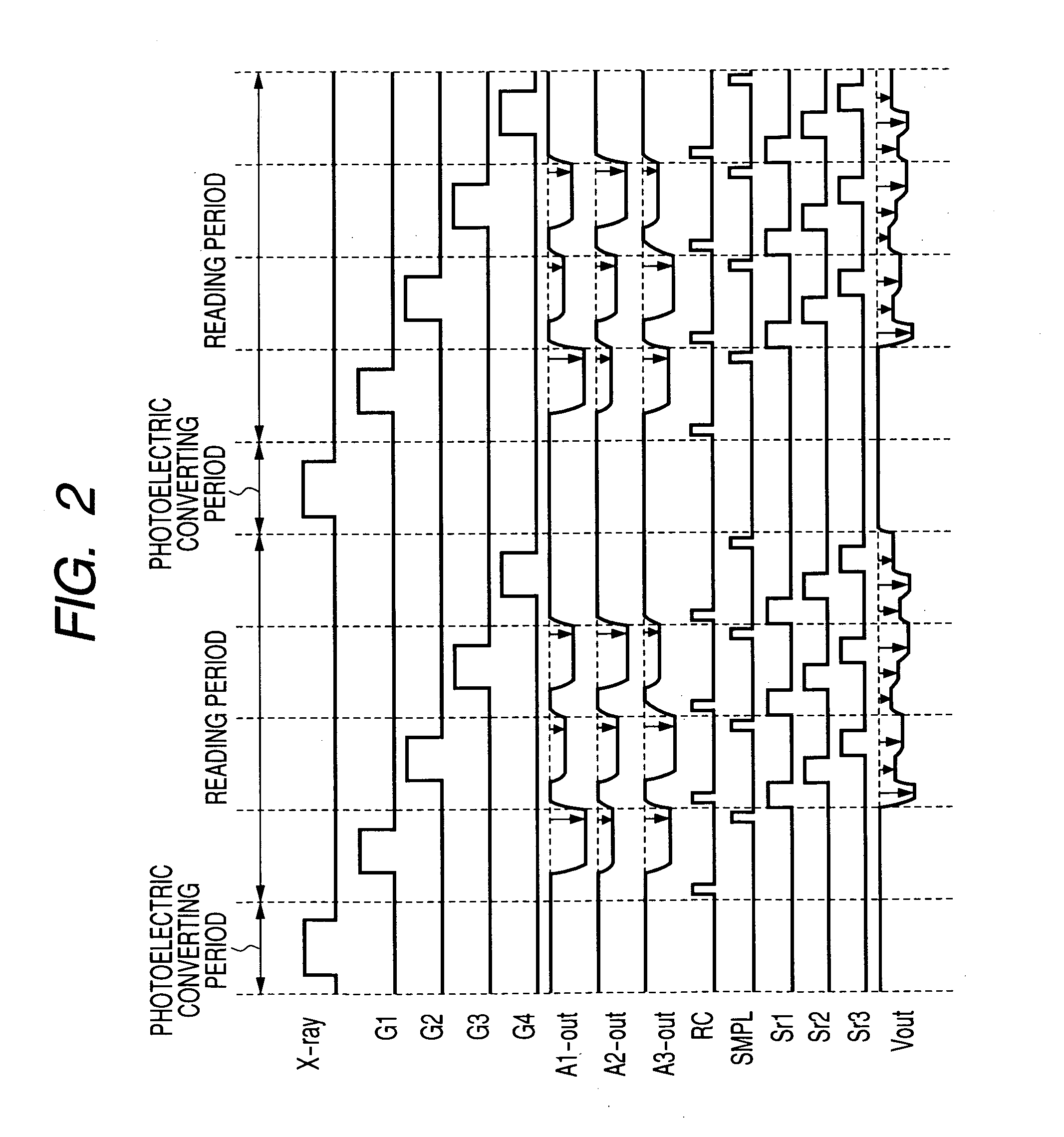
[0113] Then, third embodiment of the present invention is described below. In the case of the third embodiment, the X-ray image pickup apparatus of the second embodiment is changed from the radioscopic mode (dynamic image mode) to the radiographing mode (static image mode) in accordance with a request of an operator for radiographing a static image. FIG. 5 is an illustration showing a radiographing sequence of the X-ray image pickup apparatus of the third embodiment of the present invention. FIG. 6 is a time chart showing operations of an X-ray image pickup apparatus in the radioscopic mode (dynamic image mode) and FIG. 7 is a time chart showing operations of an X-ray image pickup apparatus in the radiographing mode (static image mode).
[0114] In the radioscopic mode, the timing operation shown in FIG. 6 is repeated. In the period of the radioscopic mode, an operator monitors the radioscopic image of a patient in order to decide the position and angle of an object ...
fourth embodiment
(Fourth Embodiment)
[0120] Then, fourth embodiment of the present invention is described below. FIG. 9 is a schematic view showing a structure of the X-ray image pickup apparatus (radiation image pickup apparatus) of the fourth embodiment of the present invention.
[0121] In the case of this embodiment, a readout circuit unit and a drive circuit unit are respectively divided into a plurality of blocks and are connected to a photoelectric conversion circuit unit. Black squares (|) in FIG. 9 respectively show one pixel and a circuit for the one pixel is shown in the circle (◯) in FIG. 9. In the case of this embodiment, an MIS-type photoelectric converting device, first TFT, second TFT and third TFT are included in pixels similarly to the case of the second embodiment. However, it is allowed to use a PIN-type photoelectric converting device as a photoelectric converting device similarly to the case of the first embodiment.
[0122] Blocks of the readout circuit unit are shown as AMP-IC1 to...
PUM
 Abstract
Description
Claims
Application Information
 - R&D
- Intellectual Property
- Life Sciences
- Materials
- Tech Scout
- Unparalleled Data Quality
- Higher Quality Content
- 60% Fewer Hallucinations
Browse by: Latest US Patents, China's latest patents, Technical Efficacy Thesaurus, Application Domain, Technology Topic, Popular Technical Reports.
© 2025 PatSnap. All rights reserved.Legal|Privacy policy|Modern Slavery Act Transparency Statement|Sitemap|About US| Contact US: help@patsnap.com


