High intensity focused ultrasound for imaging and treatment of arrhythmias

a high-intensity, focused ultrasound technology, applied in the field of arrhythmia treatment, can solve the problems of increasing mortality and morbidity, degrading the quality of life of patients, and and achieve the effect of significant reducing the overall treatment tim

Inactive Publication Date: 2005-12-01
THE BOARD OF TRUSTEES OF THE LELAND STANFORD JUNIOR UNIV
View PDF28 Cites 65 Cited by
  • Summary
  • Abstract
  • Description
  • Claims
  • Application Information

AI Technical Summary

Benefits of technology

[0014] The processing means can be gated to the heart cycle or part of the heart cycle. Gating could be established by a gating processor or a heart cycle monitoring means. In one example, the heart cycle is monitored to coincide with the timing and execution of

Problems solved by technology

A large percentage of the US population suffers from arrhythmias, irregular contractions of the heart that degrade the quality of life and increases mortality and morbidity.
This degrades a patient's quality of life and can lead to clot formation followed by strokes and other suffering.
However, widespread acceptance of ablative strategies for curing atrial fibrillation has been limited by the need for surgical intervention and the difficulty and limited success of catheter based approaches.
Long-term success with catheter-based ablations remains limited to about b 80%, despite the need for more than 1.5 procedures on average per patient.
The catheter-based procedures also remain tedious with procedure times of over 7 hours.
Some of the challenges of catheter ablation are visualization and mechanical positioning of the catheter tip.
The structures and anatomy of the heart relative to the position of the catheters are hard to determine, so it is difficult to direct the catheter to a specific site for ablation.
Second, once a lesion has been created, this location cannot be visualized

Method used


Image

  • High intensity focused ultrasound for imaging and treatment of arrhythmias
  • High intensity focused ultrasound for imaging and treatment of arrhythmias
  • High intensity focused ultrasound for imaging and treatment of arrhythmias

Examples


Embodiment Construction

[0021] Although the following detailed description contains many specifics for the purposes of illustration, anyone of ordinary skill in the art will readily appreciate that many variations and alterations to the following exemplary details are within the scope of the invention. Accordingly, the following preferred embodiments of the invention are set forth without any loss of generality to, and without imposing limitations upon, the claimed invention.

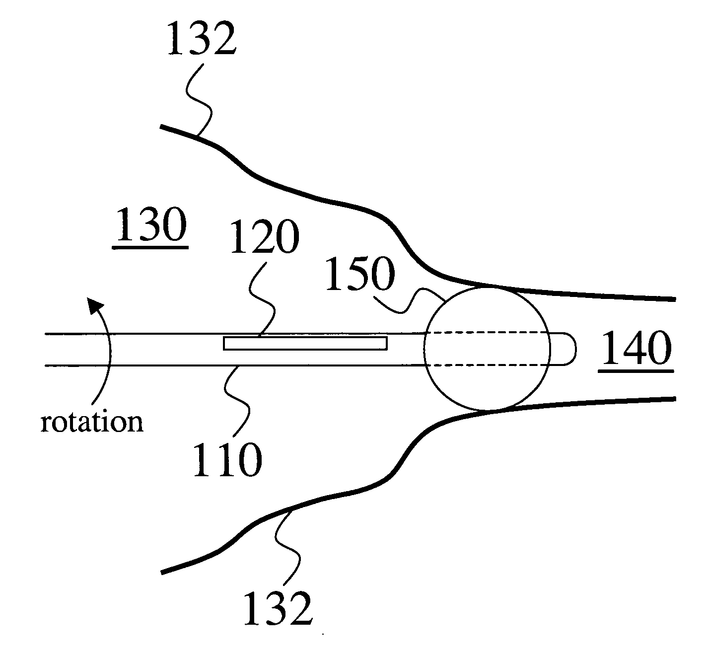
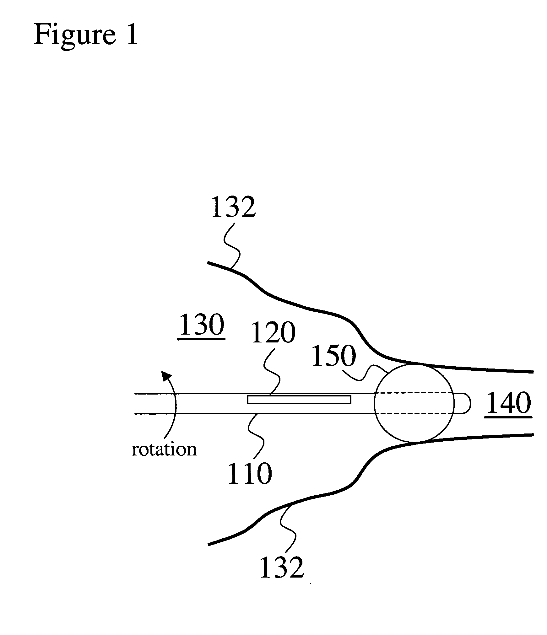
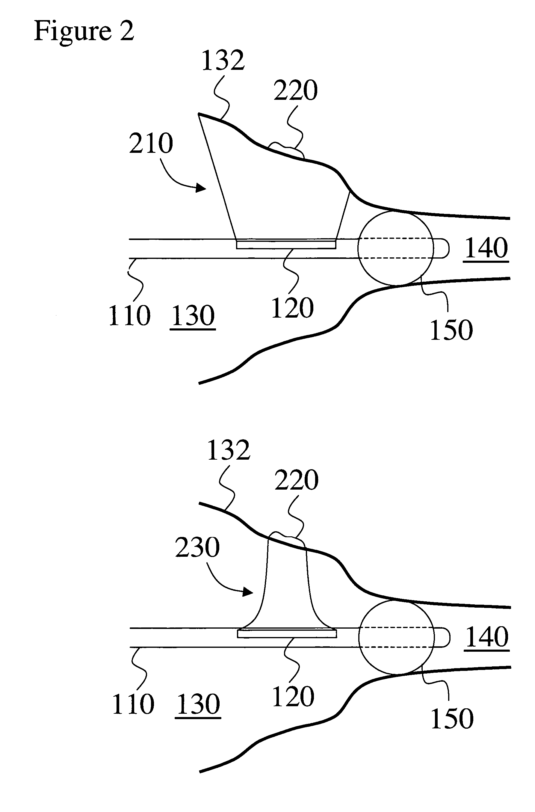
[0022] The apparatus of the present invention is a dual-mode high intensity focused ultrasound array 110 with an ablation mode and an imaging mode. Array 110 is integrated in the longitudinal direction of a catheter 120 and has a side-view with respect to catheter 120. In one aspect, the diameter of the catheter is up to 4 mm and is preferably 2-3 mm. In yet another aspect, the catheter is a 7-French catheter with a diameter of about 2.31 mm. The length of the array should be at least 15 mm and is preferably about 20-30 mm. The width ...


PUM


Abstract

A dual-mode, capable of imaging and ablation, ultrasound array integrated in a catheter is provided for minimally invasive treatment of arrhythmias. The catheter array is small enough for insertion through a peripheral vein and is longitudinally integrated with the catheter to have a side-view for tissue imaging and ablation. A high length/width array ratio creates a large aperture necessary for high power ablation densities. A catheter stabilization device maintains a distance between the catheter array and the wall of a heart or vein. Visualization of anatomy and imaging of ablated tissue provides a guide for placing the lesion and assists in achieving a pattern of ablated tissue. The catheter is advanced to another area by catheter rotation and/or array steering or focusing. Gating the imaging and ablation processes to a heart cycle allows for accounting and compensation of heart motion and enables automation of an arrhythmia treatment.

Description

CROSS-REFERENCE TO RELATED APPLICATIONS [0001] The present application claims priority from U.S. Provisional Patent Application with No. 60 / 575,455 filed on May 27, 2004, the entire content of which is incorporated herein by reference.FIELD OF THE INVENTION [0002] The present invention relates generally to treatments of arrhythmias. More particularly the invention relates to intravascular imaging and treatment of atrial fibrillation with a single dual mode high intensity focused ultrasound array. BACKGROUND [0003] A large percentage of the US population suffers from arrhythmias, irregular contractions of the heart that degrade the quality of life and increases mortality and morbidity. In particular, atrial fibrillation (AF) affects about 1% of the population and is responsible for 15-20% of all strokes; this results in more than 460,000 hospitalizations ($2.8 billion from hospitalizations alone) per year. [0004] AF is caused by the breakdown of ordered electrical propagation within ...

Claims


Application Information

Patent Timeline
IPC IPC(8): A61B8/00A61B8/12A61B17/00A61B18/04A61B19/00A61N7/02
CPCA61B8/12A61B8/445A61B8/4488A61N7/022A61B2017/00243A61B2019/5278A61B8/543A61B2090/3782
Inventor WONG, SERENA H.LIANG, DAVID H.NARAYAN, GIRISH
Owner THE BOARD OF TRUSTEES OF THE LELAND STANFORD JUNIOR UNIV
Why Eureka
Try Eureka