Metal bellows position feedback for hydraulic control of an adjustable gastric band

a gastric band and metal bellows technology, applied in the field of medical implantable reversible pumps, can solve the problems of affecting the operation of the gastric band, so as to achieve accurate, closed-loop motion control of the bellows accumulator

a gastric band and metal bellows technology, applied in the field of medical implantable reversible pumps, can solve the problems of affecting the operation of the gastric band, so as to achieve accurate, closed-loop motion control of the bellows accumulator

US20050267500A1Inactive Publication Date: 2005-12-01ETHICON ENDO SURGERY INC

Image

  • Metal bellows position feedback for hydraulic control of an adjustable gastric band
  • Metal bellows position feedback for hydraulic control of an adjustable gastric band
  • Metal bellows position feedback for hydraulic control of an adjustable gastric band

Examples


Embodiment Construction

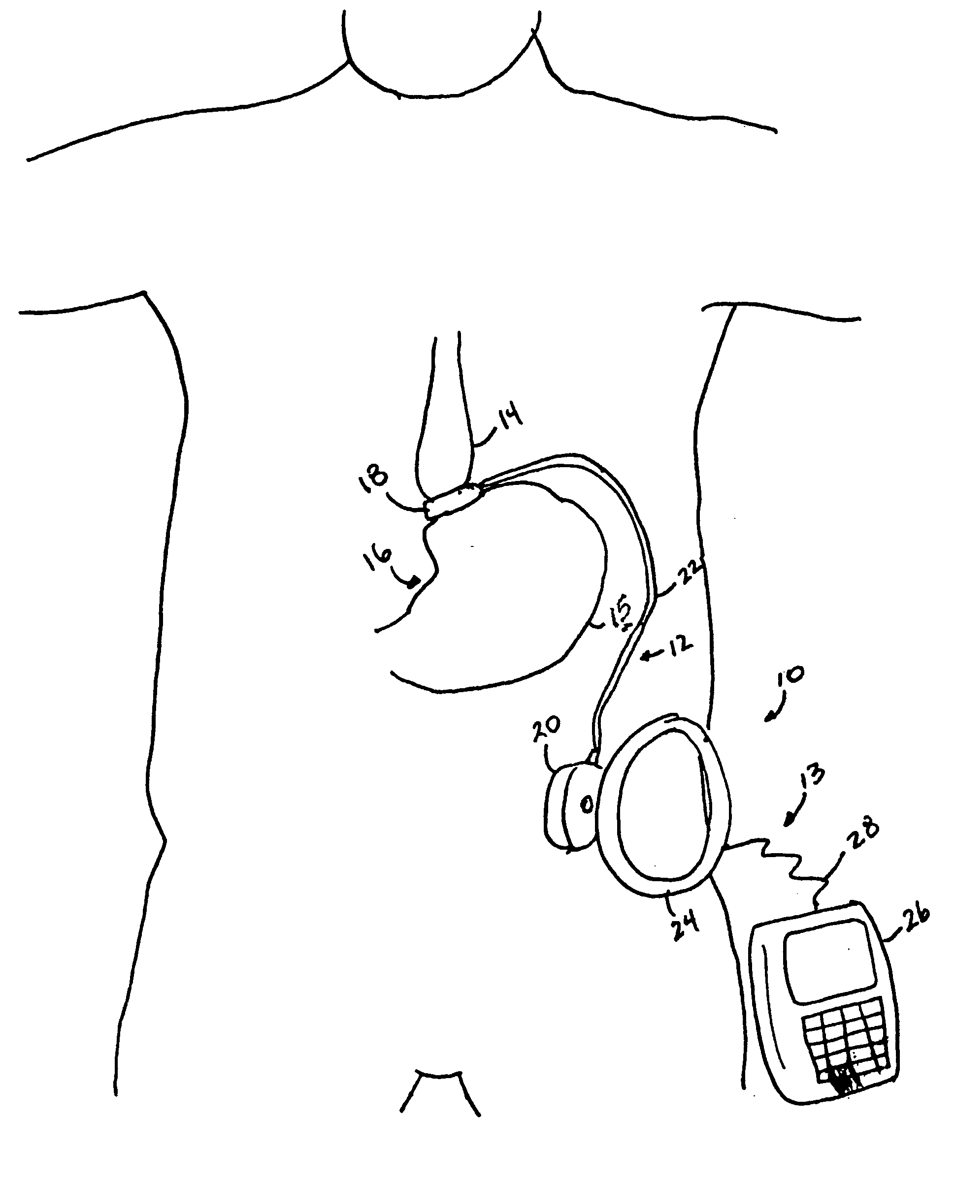
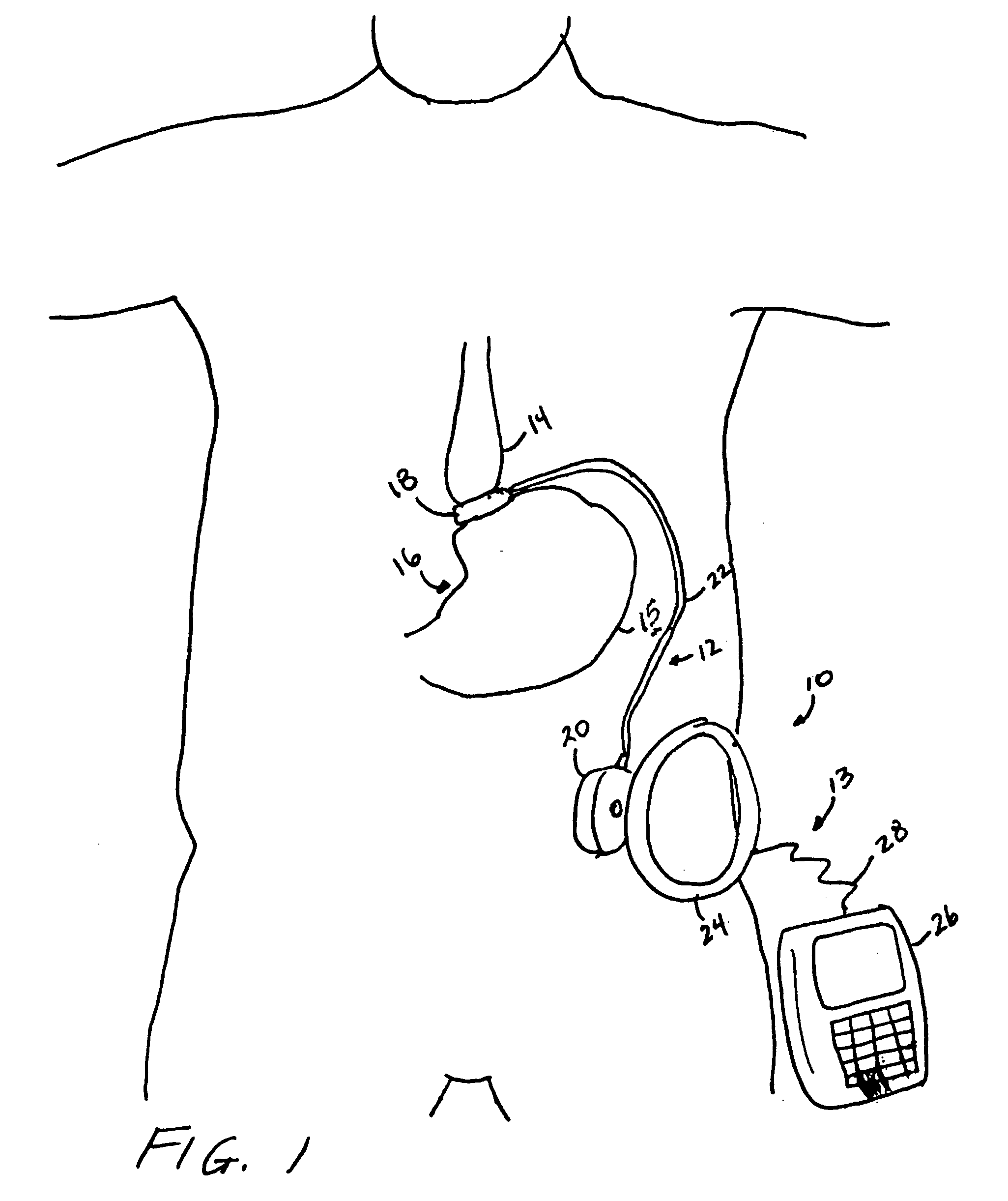
[0031] Turning to the Drawings wherein like numerals denote like components throughout the several views, in FIG. 1, an artificial sphincter system 10 regulates the amount of fluid maintained in an implantable artificial sphincter assembly 12 powered by transcutaneous energy transfer (TET) and under telemetry control of an external assembly 13. In the illustrative version, the artificial sphincter system 10 is used for weight reduction therapy. A stoma is formed between an upper portion 14 and lower portion 15 of a patient's stomach 16 to slow the passage of food and to provide a sense of fullness. The implantable artificial sphincter assembly 12 includes an expandable gastric band 18 that encircles the stomach 16 to form the stoma. An infuser device 20 is anchored subcutaneously on a layer of muscular fascia within the patient or in another convenient location. A flexible catheter 22 provides fluid communication between the gastric band 18 and the infuser device 20.

[0032] It shoul...


PUM


Abstract

A remotely controlled gastric band system that is practically immune to external magnetic fields, such as from a Magnetic Resonance Imaging (MRI) machine, incorporates a bi-directional pump and fluid reservoir to adjust fluid volume for hydraulic control of a gastric band. A piezoelectric driver (e.g., rotary actuator, linear actuator) selectively compresses and expands a metal bellows hermetically sealed within a biocompatible and nonferromagnetic enclosure or case such as titanium. Directly sensing a position of the metal bellows yields an accurate reading of volume contained therein, allowing for closed-loop control of the gastric band.

Description

CROSS REFERENCE TO RELATED APPLICATIONS [0001] The present application is related to three co-pending and commonly-owned applications filed on even date herewith, the disclosure of each being hereby incorporated by reference in their entirety, entitled respectively: [0002]“PIEZO ELECTRICALLY DRIVEN BELLOWS INFUSER FOR HYDRAULICALLY CONTROLLING AN ADJUSTABLE GASTRIC BAND” to William L. Hassler, Jr., Ser. No. ______; [0003]“THERMODYNAMICALLY DRIVEN REVERSIBLE INFUSER PUMP FOR USE AS A REMOTELY CONTROLLED GASTRIC BAND” to William L. Hassler, Jr., Daniel F. Dlugos, Jr., Ser. No. ______; and [0004]“BI-DIRECTIONAL INFUSER PUMP WITH VOLUME BRAKING FOR HYDRAULICALLY CONTROLLING AN ADJUSTABLE GASTRIC BAND” to William L. Hassler, Jr., Daniel F. Dlugos, Jr., Ser. No. ______.FIELD OF THE INVENTION [0005] The present invention relates, in general, to medically implantable reversible pumps, and more particularly, to such pumps that are suitable for long term use without fluid loss such as for hyd...

Claims


Application Information

Patent Timeline
01 Dec 2005
Publication
US20050267500A1
IPC
A61B17/00; A61F2/00; A61F5/00
CPC
A61F5/0003
Inventors
HASSLER, WILLIAM L. JR.; DLUGOS, DANIEL F. JR.