Gasification apparatus and method

a gasification apparatus and gasification method technology, applied in the field of gasification, can solve the problems of difficult to consistently produce gases having sufficiently high heating values, the heating value of gases produced using prior art systems has tended to fluctuate to an undesirable degree, and the gasification has only met with limited success, so as to achieve safe and clean consumption, safe and efficient handling and dry, and easy processing a wide variety of combinations

Inactive Publication Date: 2005-12-08
POWER RECLAMATION
View PDF41 Cites 15 Cited by
  • Summary
  • Abstract
  • Description
  • Claims
  • Application Information

AI Technical Summary

Benefits of technology

[0006] It is therefore an object of the present invention to provide a flexible gasification apparatus and method that provides combustible gases having high heating values while avoiding pitfalls of prior attempts at gasification.
[0007] It is a further object of the present invention to provide an apparatus and method of the above type that can easily handle a wide variety of carbonaceous fuel sources or combinations of fuel sources.
[0008] It is a further object of the present invention to provide an apparatus and method of the above type that produces a high value heating gas having low amounts of particulate matter and other pollutants.

Problems solved by technology

Despite these obvious advantages, gasification has met with only limited success, because gasification systems have typically been plagued by a number of disadvantages or difficulties.
For example, the heating values of gases produced using prior art systems have tended to fluctuate to an undesirable degree, particularly when a variety of fuel sources or fuel sources of varying compositions have been used.
Similarly, it has also proven difficult to consistently produce gases having sufficiently high heating values.
Separating particulate matter from the produced gas has proven problematic.
Similarly, it has proven difficult to produce sufficiently clean gases having sufficiently low amounts of particulate matter as well as sufficiently low amounts of pollutants such as such as sulfur dioxide (SO2), nitrogen oxides (NOx), carbon monoxide (CO), volatile organic compounds (VOC), ammonia (NH3), hydrogen chloride (HCl), and other chlorides.
Environmentally sound disposal of wastewater generated by such systems has also presented difficulties.
Further still, the presence of water or other liquids in the combustible gas has made it difficult or impossible to use blowers for moving the combustible gases without creating undesirable levels of wear and tear on the blowers.

Method used


Image

  • Gasification apparatus and method
  • Gasification apparatus and method
  • Gasification apparatus and method

Examples


example 1

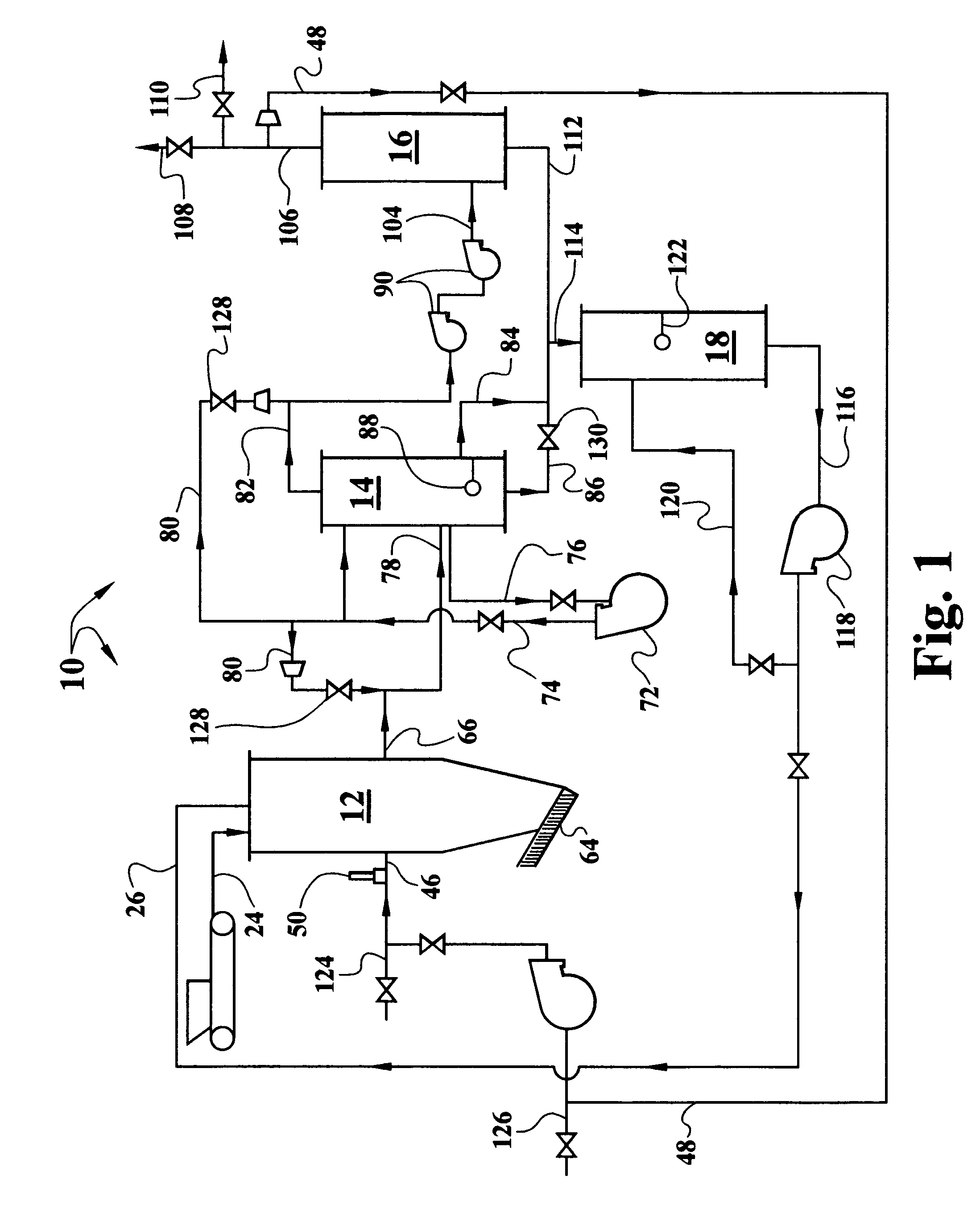
[0044] An emissions test was conducted on combustible gas generated by the system 10 while combusting chicken litter. A sample run of 60 minutes in duration was performed. Testing was performed in accordance with the methods detailed in 40 Code of Federal Regulations (CFR), Part 60, Appendix A. The flow, based on the lowest recordable flow, had a velocity of 6.77 feet per second, and the sample collected had a volume of 41.42 dry standard cubic feet. The results of the emissions testing are summarized in Table 1 below.

TABLE 1EmissionsSubstance(lbs / hr)Particulate Matter (based on lowest detectable flow rate)0.003VOC as Propane (corrected for moisture)0.137Nitrogen Oxides as NO20.001Carbon Monoxide0.003Sulfur Dioxide0.096Ammonia0.033HCl0.008Chloride0.005

example 2

[0045] An emissions test was conducted on combustible gas generated by the system 10 while combusting paper mill sludge. A sample run of 60 minutes in duration was performed. Testing was performed in accordance with the methods detailed in 40 CFR, Part 60, Appendix A. The flow, based on the lowest recordable flow, had a velocity of 6.53 feet per second, and the sample collected had a volume of 40.60 dry standard cubic feet. The results of the emissions testing are summarized in Table 2 below.

TABLE 2EmissionsSubstance(lbs / hr)Particulate Matter (based on lowest detectable flow rate)0.0014VOC as Propane (corrected for moisture)0.014Nitrogen Oxides as NO20.013Carbon Monoxide0.051Sulfur Dioxide0.017

[0046] Other modifications, changes and substitutions are intended in the foregoing, and in some instances, some features of the invention will be employed without a corresponding use of other features. For example, the configuration of the ash support member 36 may be used in combination wi...


PUM

PropertyMeasurementUnit
heightaaaaaaaaaa
heightaaaaaaaaaa
velocityaaaaaaaaaa

Abstract

A gasification system is disclosed having a combustor, a scrubber, a finisher, and optionally a recycler. A carbonaceous fuel is partially combusted in the combustor to generate a combustible gas. An improved ash support and removal system reduces clogging and other problems in the combustor. The combustible gas passes through the scrubber to remove matter such as tar and oil and to undergo preliminary catalytic chemical reactions. The scrubbed gas passes through a hybrid blower to the finisher. Final catalytic chemical reactions occur in the finisher, and wood chips or other filters may also be used in the finisher to provide a relatively clean, dry, combustible gas. Wastewater and other waste products from the scrubber and finisher are captured in the recycler and returned to the combustor.

Description

CROSS-REFERENCE TO RELATED APPLICATIONS [0001] This application is a continuation-in-part of co-pending U.S. patent application Ser. No. 10 / 911,386, filed Aug. 4, 2004, which claims benefit of U.S. Provisional Patent Application Ser. No. 60 / 492,363, filed Aug. 4, 2003. Each of the aforementioned related patent applications is herein incorporated by reference in its entirety.BACKGROUND OF THE INVENTION [0002] 1. Field of the Invention [0003] This invention relates to gasification and, more particularly, to a flexible gasification apparatus and method that provides combustible gases having high heating values while avoiding pitfalls of prior attempts at gasification. [0004] 2. Description of the Related Art [0005] Gasification has generally been known for years. In gasification, a carbonaceous fuel source is partially combusted to produce a combustible gas, synthesis gas, or syngas. The combustible gas is then combusted to produce work. The combustible gases produced by gasification m...

Claims


Application Information

Patent Timeline
Patent Type & Authority Applications(United States)
IPC IPC(8): C10J3/00C10J3/26C10J3/42
CPCB01D53/14C10K1/34C10J3/30C10J3/32C10J3/34C10J3/42C10J3/723C10J2200/158C10J2300/0956C10J2300/0973C10J2300/1807C10K1/024C10K1/08C10K1/101C10J3/26
Inventor ROGERS, MICHAEL W.
Owner POWER RECLAMATION
Why Eureka
Try Eureka