Digital amplitude modulation

Active Publication Date: 2005-12-08
TEXAS INSTR INC
View PDF17 Cites 88 Cited by
  • Summary
  • Abstract
  • Description
  • Claims
  • Application Information

AI Technical Summary

Benefits of technology

[0011] The present invention provides significant advantages over the prior art. First, a solution having an all digital amplitude modulation path and an all digital phase modulation path increas

Problems solved by technology

A major weakness of this mixer-based transmitter architecture is that even a small mismatch in phase shift or amplitude gain between the I and Q paths can significantly impair the system performance.
Furthermore, because of a certai

Method used


Image

  • Digital amplitude modulation
  • Digital amplitude modulation
  • Digital amplitude modulation

Examples


first embodiment

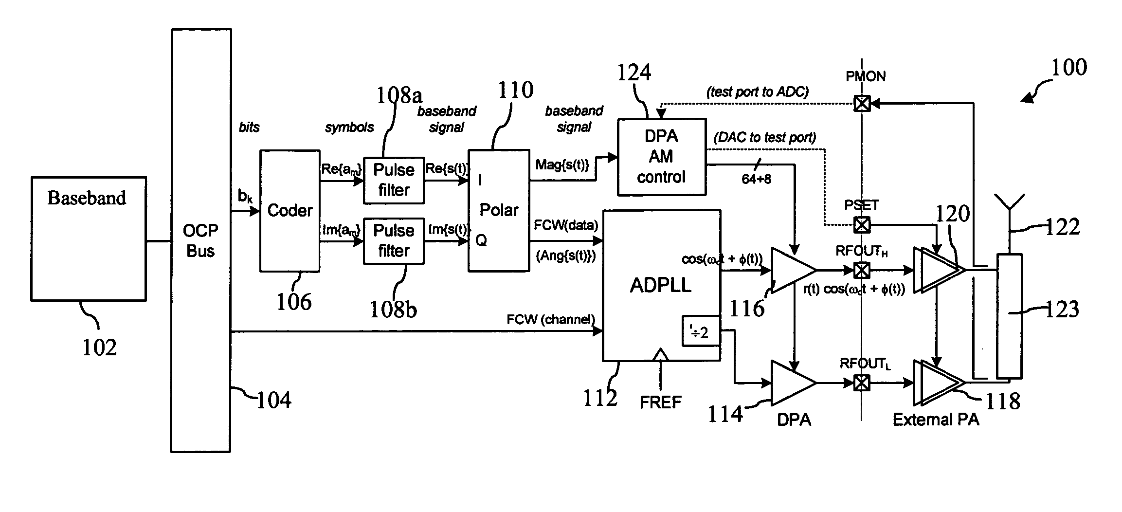
[0042]FIG. 10 illustrates a DPA 128, which could be used for DPA 114 or 116. The 64+8 bits output from AM control circuit 124 are coupled to the gates of respective n-channel CMOS transistors 130. Each transistor 130 has source / drains coupled in series with a respective n-channel transistor 132 between voltage rail 134 and ground. N-channel transistors 132 have gates coupled to the output of the ADPLL 112. Voltage rail 134 is coupled to matching network 136, for converting the switch state (its resistance or drain current) to a sinusoid. Resistor RL represents the input impedance of the external power amplifier.

[0043] In operation, the main attribute of the DPA 128 of FIG. 10 is low noise. The thermometer code output of AM control 124 determines how many transistors 130 are enabled. The RF amplitude is digitally controlled by regulating the number of active switches in accordance with the desired instantaneous amplitude.

second embodiment

[0044]FIG. 11 illustrates a DPA 140, where the 64+8 bits output from the AM control circuit 124 drive one input of respective AND gates 142. The other input of each AND gate 142 is driven by the output of the ADPLL 112. Each AND gate 142 drives the gate of an n-channel transistor 144, where each n-channel transistor has source / drains coupled between a matching network input, voltage rail 146 and ground. A matching network 148 is coupled between the voltage rail, transistor switches output 146 and the external power amplifier.

[0045] In operation, the DPA 140 improves on the carrier leakage of DPA 128 of FIG. 10. The AND gates 142 may be implemented as a complementary pass gate with a pull-down n-channel transistor. Similar to FIG. 10, the output of AM control circuit 124 determines the number of transistors 144 that are dynamically enabled.

[0046]FIG. 12 illustrates a block diagram of a preferred embodiment for the AM control circuit 124. The AM control circuit receives the clock, CK...


PUM


Abstract

A transmitter using quadrature modulation includes a rectangular to polar converter for converting data symbols into a polar form, where each polar symbol has a magnitude signal and an angle signal. Digital phase modulation circuitry includes an all digital PLL circuit for generating a phase modulated RF carrier signal responsive to the angle signal frequency control word (FCW) and a carrier frequency FCW. A digitally controlled amplifier for amplifying the phase modulated signal is controlled by a digital amplitude control circuitry for controlling the gain of the digitally controlled amplifier responsive to the magnitude signal.

Description

CROSS-REFERENCE TO RELATED APPLICATIONS [0001] Not Applicable STATEMENT OF FEDERALLY SPONSORED RESEARCH OR DEVELOPMENT [0002] Not Applicable BACKGROUND OF THE INVENTION [0003] 1. Technical Field [0004] This invention relates in general to communication devices and, more particularly, to a fully digital method and apparatus for amplitude and phase modulation. [0005] 2. Description of the Related Art [0006] Quadrature modulation is commonly used for communication. FIG. 1 shows a conventional prior art direct up-conversion transmitter 10. The in-phase (I) and quadrature (Q) pulse-shaped digital baseband signals from the digital baseband 12 are converted into analog domain with digital-to-analog (D / A) converters 14. Due to their digital nature, the D / A outputs exhibit strong sampling-time harmonics and switching noise, which have to be conditioned with low-pass filters (LPF) 16 before being up-converted to the RF carrier by a modulator 18, which is a critical RF / analog block. The RF fre...

Claims


Application Information

Patent Timeline
IPC IPC(8): H03F1/02H03F1/06H03F1/32H03F3/24H04K1/02H04L27/20H04L27/36
CPCH03F1/0205H03F1/0211H03F1/32H03F3/24H03F2200/331H03F2200/451H04L27/361
Inventor STASZEWKI, ROBERT B.REZEQ, SAMEHLEIPOLD, DIRK
Owner TEXAS INSTR INC
Why Eureka
Try Eureka