Controlled vapor deposition of multilayered coatings adhered by an oxide layer

a multi-layer coating and oxide layer technology, applied in the direction of coatings, transportation and packaging, chemical instruments and processes, etc., can solve the problem of repetitive individual steps, achieve excellent results, improve mechanical strength and rigidity of multi-layer coatings, and increase the overall thickness of multi-layer coatings

Inactive Publication Date: 2005-12-08
APPLIED MICROSTRUCTURES
View PDF31 Cites 51 Cited by
  • Summary
  • Abstract
  • Description
  • Claims
  • Application Information

AI Technical Summary

Benefits of technology

[0034] The coatings formed by the method of the invention can be sufficiently controlled so that the surface roughness of the coating in terms of RMS is less than about 10 nm, and is typically in the range of about 0.5 nm to 5 nm.
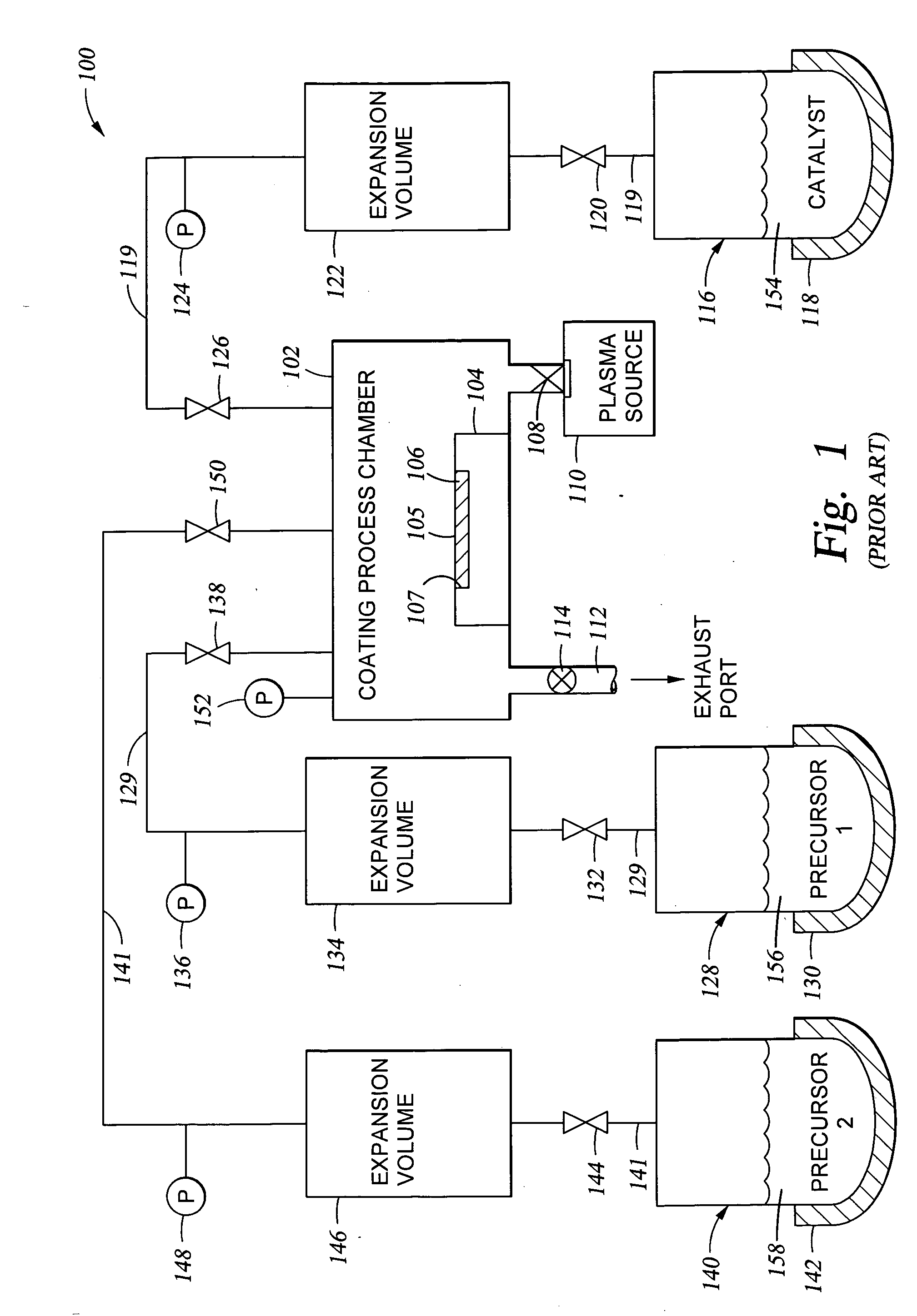
[0044] After deposition of a first organic-based layer, and prior to the deposition of an overlying layer in a multilayered coating, it is advisable to use an in-situ oxygen plasma treatment. This treatment activates reaction sites of the first organic-based layer and may be used as part of a process for generating an oxide-based layer or simply to activate dangling bonds on the substrate surface. The activated dangling bonds may be exploited to provide reactive sites on the substrate surface. For example, an oxygen plasma treatment in combination with a controlled partial pressure of water vapor may be used to create a new concentration of OH reactive species on an exposed surface. The activated surface is then used to provide covalent bonding with the next layer of material applied. A deposition process may then be repeated, increasing the total coating thickness, and eventually providing a surface layer having the desired surface properties. In some instances, where the substrate surface includes metal atoms, treatment with the oxygen plasma and moisture provides a metal oxide-based layer containing —OH functional groups. This oxide-based layer is useful for increasing the overall thickness of the multilayered coating and for improving mechanical strength and rigidity of the multilayered coating.

Problems solved by technology

Some of the individual steps may be repetitive.

Method used


Image

  • Controlled vapor deposition of multilayered coatings adhered by an oxide layer
  • Controlled vapor deposition of multilayered coatings adhered by an oxide layer
  • Controlled vapor deposition of multilayered coatings adhered by an oxide layer

Examples


example one

[0087] Deposition of a Silicon Oxide Layer Having a Controlled Number of OH Reactive Sites Available On the Oxide Layer Surface

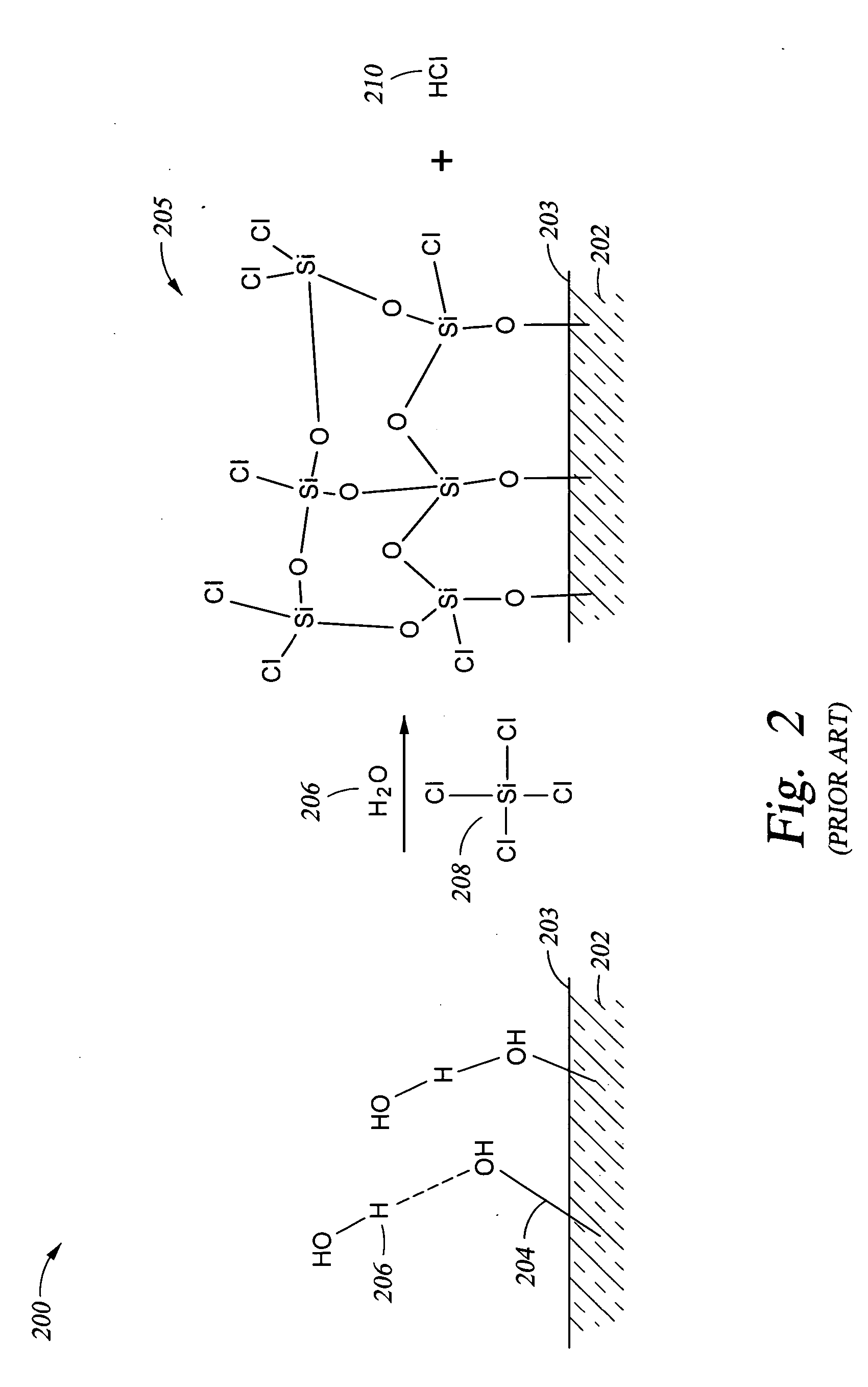
[0088] A technique for adjusting the hydrophobicity / hydrophilicity of a substrate surface (so that the surface is converted from hydrophobic to hydrophilic or so that a hydrophilic surface is made more hydrophilic, for example) may also be viewed as adjusting the number of OH reactive sites available on the surface of the substrate. One such technique is to apply an oxide coating over the substrate surface while providing the desired concentration of OH reactive sites available on the oxide surface. A schematic 200 of the mechanism of oxide formation in shown in FIG. 2. In particular, a substrate 202 has OH groups 204 present on the substrate surface 203. A chlorosilane 208, such as the tetrachlorosilane shown, and water 206 are reacted with the OH groups 204, either simultaneously or in sequence, to produce the oxide layer 208 shown on surface 203 of subst...

example two

[0090] In the preferred embodiment discussed below, a silicon oxide coating was applied over a glass substrate. The glass substrate was treated with an oxygen plasma in the presence of residual moisture which was present in the process chamber (after pump down of the chamber to about 20 mTorr) to provide a clean surface (free from organic contaminants) and to provide the initial OH groups on the glass surface.

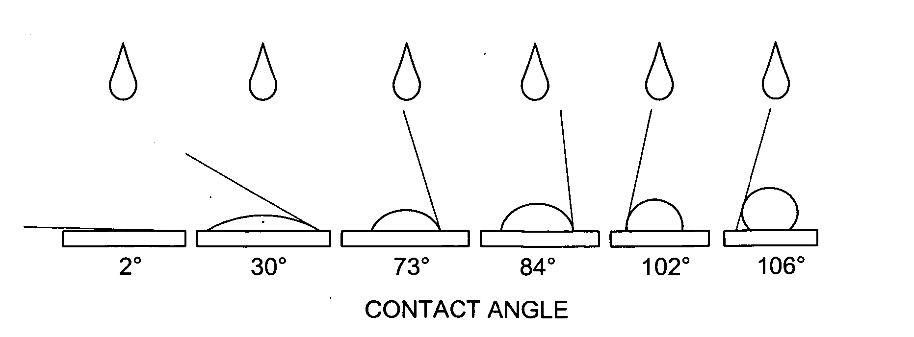
[0091] Various process conditions for the subsequent reaction of the OH groups on the glass surface with vaporous tetrachlorosilane and water are provided below in Table I, along with data related to the thickness and roughness of the oxide coating obtained and the contact angle (indicating hydrophobicity / hydrophilicity) obtained under the respective process conditions. A lower contact angle indicates increased hydrophilicity and an increase in the number of available OH groups on the silicon oxide surface.

TABLE IDeposition of a Silicon Oxide Layer of Varying HydrophilicityP...

example three

[0099] When the oxide-forming silane and the organo-silane which includes the functional moiety are deposited simultaneously (co-deposited), the reaction may be so rapid that the sequence of precursor addition to the process chamber becomes critical. For example, in a co-deposition process of SiCl4 / FOTS / H2O, if the FOTS is introduced first, it deposits on the glass substrate surface very rapidly in the form of islands, preventing the deposition of a homogeneous composite film. Examples of this are provided in Table III, below.

[0100] When the oxide-forming silane is applied to the substrate surface first, to form the oxide layer with a controlled density of potential OH reactive sites available on the surface, the subsequent reaction of the oxide surface with a FOTS precursor provides a uniform film without the presence of agglomerated islands of polymeric material, examples of this are provided in Table III below.

TABLE IIIDeposition of a Coating Upon a Silicon Substrate*Using Sil...


PUM

PropertyMeasurementUnit
partial pressureaaaaaaaaaa
temperatureaaaaaaaaaa

Abstract

An improved vapor-phase deposition method and apparatus for the application of multilayered films / coatings on substrates is described. The method is used to deposit multilayered coatings where the thickness of an oxide-based layer in direct contact with a substrate is controlled as a function of the chemical composition of the substrate, whereby a subsequently deposited layer bonds better to the oxide-based layer. The improved method is used to deposit multilayered coatings where an oxide-based layer is deposited directly over a substrate and a SAM organic-based layer is directly deposited over the oxide-based layer. Typically a series of alternating layers of oxide-based layer and organic-based layer are applied.

Description

[0001] This application is a continuation-in-part application of U.S. patent application Ser. No. 10 / 862,047, filed Jun. 4, 2004 and entitled “Controlled Deposition of Silicon-Containing Coatings Adhered By An Oxide Layer”, which is currently pending. Application Ser. No. 10 / 862,047 is related to, but does not claim priority under Provisional Application Ser. No. 60 / 482,861, filed Jun. 27, 2003 and entitled: “Method And Apparatus for Mono-Layer Coatings”; Provisional Application Ser. No. 60 / 506,846, filed Sep. 30, 2003, and entitled: “Method Of Thin Film Deposition”; Provisional Application Ser. No. 60 / 482,861, filed Oct. 9, 2003, and entitled: “Method of Controlling Monolayer Film Properties”; and, to U.S. patent application Ser. No. 10 / 759,857, filed Jan. 16, 2004, which claims priority under the provisional applications listed above.BACKGROUND OF THE INVENTION [0002] 1. Field of the Invention [0003] The present invention pertains to a method, and to the resulting structure which ...

Claims


Application Information

Patent Timeline
Patent Type & Authority Applications(United States)
IPC IPC(8): B05D3/14B05D7/00B05D7/24B21D39/00B32B9/00B32B15/04C23C16/00C23C16/02C23C16/40C23C16/448C23C16/455C23C16/56
CPCB05D1/185Y10T428/24B05D3/142B05D3/145B05D7/52B05D7/56B82Y30/00B82Y40/00C03C17/42C03C23/006C23C16/0227C23C16/0245C23C16/0272C23C16/401C23C16/402C23C16/448C23C16/4485C23C16/455C23C16/45557C23C16/56Y10T428/31667Y10T428/31663Y10T428/24355Y10T428/24975Y10T428/12618Y10T428/265Y10T428/12632Y10T428/261Y10T428/24967B05D1/60
Inventor KOBRIN, BORISCHINN, JEFFREY D.NOWAK, ROMUALDYI, RICHARD C.
Owner APPLIED MICROSTRUCTURES
Why Eureka
Try Eureka