Photoactive compounds
a technology of photoactive compounds and compounds, applied in the field of new materials, can solve the problems of critical edge roughness and adverse effects of photoresist pattern roughness on and achieve the effect of improving the lithographic performance of the photoresis
- Summary
- Abstract
- Description
- Claims
- Application Information
AI Technical Summary
Benefits of technology
Problems solved by technology
Method used
Image
Examples
example 1
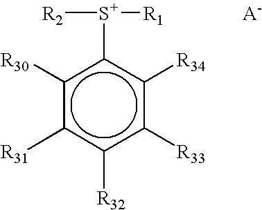
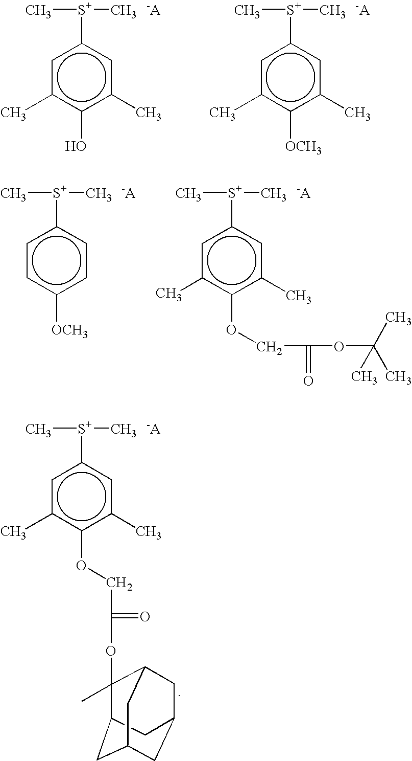
Synthesis of 3,5-dimethyl-4-hydroxyphenyldimethyl sulfonium tetrafluoroethoxy octafluorobutane sulfonate
[0064] 3,5-dimethyl-4-hydroxyphenyldimethyl sulfonium chloride (5 g, 0.0229 mole) was dissolved in 150 ml water in a suitable vessel. Lithium tetrafluoroethoxy octafluorobutane sulfonate (17.12 g at 54.4% solid in water) was added with stirring at room temperature. The mixture was stirred for two hours and extracted with chloroform. The organic phase was washed with deionized water (4×200 ml) and the organic (chloroform) layer was dried over anhydrous sodium sulfate and filtered. The chloroform was evaporated using a vacuum evaporator and a colored oil remained. The colored oil was washed several times with hexane. Yield, 40% oil. 1H NMR (Acetone d6): 2.35 (s, 6H, 2CH3), 3.4 (s, 6H, 2CH3), 6.9-7.25,1H, 7.80 (s, 2H, aromatic).
example 1a
Alternate Synthesis of 3,5-dimethyl-4-hydroxyphenyldimethyl sulfonium tetrafluoroethoxy octafluorobutane sulfonate
[0065] 3,5-dimethyl-4-hydroxyphenyldimethyl sulfonium chloride (50 g, 0.23 mole) was dissolved in 450 ml water, lithium tetrafluoroethoxy octafluorobutane sulfonate (200.2 g at 46.4% solid in water) was added with stirring at room temperature. The mixture was stirred for two hours and extracted with chloroform (900 ml). Chloroform was evaporated under vacuum and hexane was added and the mixture was stirred for 30 minutes. The hexane layer was removed and ether (700 ml) was added. A precipitate formed and the mixture was filtered with the precipitate being retained. The precipitate was added to methylene chloride and reprecipitated from ether and filtered. The remaining solid was dried in a vacuum oven at less than 40° C. The resulting crystals had a melting point of 71° C. 1H NMR (Acetone-d6), 2.35 (s, 6H, 2×CH3), 3.4 (s, 6H, 2CH3); 6.9-7.25, 1H, 7.80 (s, 2H, aromatic)....
example 2
Synthesis of 3,5-dimethyl-4-hydroxyphenyldimethyl sulfonium trifluoroethoxy octafluorobutane sulfonate
[0066] In a similar manner to that of Example 1, 2.185 g (0.01 mole) of 3,5-dimethyl-4-hydroxyphenyldimethyl sulfonium chloride was reacted with lithium trifluoroethoxy octafluorobutane sulfonate (3.86 g at 7.72% solid in water). An oil was extracted as in Example 1. Yield, 65% oil.
PUM
| Property | Measurement | Unit |
|---|---|---|
| Wavelength | aaaaa | aaaaa |
| Alkalinity | aaaaa | aaaaa |
Abstract
Description
Claims
Application Information
 - R&D
- Intellectual Property
- Life Sciences
- Materials
- Tech Scout
- Unparalleled Data Quality
- Higher Quality Content
- 60% Fewer Hallucinations
Browse by: Latest US Patents, China's latest patents, Technical Efficacy Thesaurus, Application Domain, Technology Topic, Popular Technical Reports.
© 2025 PatSnap. All rights reserved.Legal|Privacy policy|Modern Slavery Act Transparency Statement|Sitemap|About US| Contact US: help@patsnap.com


