Permanent resist composition, cured product thereof, and use thereof

a technology of permanent resist and epoxy resin, which is applied in the field of photoimageable epoxy resin compositions and the permanent cure products thereof, can solve the problems of reducing radiation intensity, thickness limitation, and conventional positive resists based on diazonaphthoquinone-novolac chemistry, and achieves the effect of improving film adhesion and increasing film density

Inactive Publication Date: 2005-11-24
MICROCHEM CORP +1
View PDF47 Cites 64 Cited by
  • Summary
  • Abstract
  • Description
  • Claims
  • Application Information

AI Technical Summary

Benefits of technology

[0026] Still another aspect of the present invention is directed to a method of forming a permanent photoresist pattern comprising: the process steps of: (1) applying any of the photoresist compositions according to the invention to a substrate; (2) evaporating most of the solvent by heating the coated substrate to form a film of the composition on the substrate; (3) irradiating the film on a substrate by active rays through a mask; (4) crosslinking the irradiated film segments by heating; (5) developing the image in the film with a solvent to form a negative-tone relief image of the mask in the photoresist film; and optionally; (6) heat-treating the developed photoresist film to complete crosslinking, increase the density of the film, and improve adhesion of the film to the coated substrate.

Problems solved by technology

Conventional positive resists based on diazonaphthoquinone-novolac chemistry are not well-suited to applications requiring film thicknesses greater than about 50 microns.
This thickness limitation is caused by the relatively high optical absorbance of the diazonaphthaquinone-type (DNQ) photoactive compounds at wavelengths in the near-ultraviolet region of the optical spectrum (350-450 nm) which are typically used to expose the resist.
Also, DNQ-type photoresists possess limited contrast, or differential solubility, of the exposed vs. unexposed resist in a developer solution which results in relief image sidewalls that are sloped rather than vertical.
Optical absorption necessarily reduces the radiation intensity as it traverses from the top to the bottom of the film, such that if the optical absorption is too high, the bottom of the film will be underexposed relative to the top, causing a sloped or otherwise distorted profile of the developed image.
While the SU-8 resin based compositions disclosed are capable of very high resolution and aspect ratio, the cured resin by itself has a tendency to be too brittle for some applications, and often undergoes developer induced crazing / cracking, stress-induced cracking, has limited adhesion to certain substrates, and sometimes demonstrates delamination of the coating from the substrate.
All these problems are exacerbated by the shrinkage-induced stress that occurs when the material undergoes polymerization and is manifested in substrate bowing, where the shrinkage of the coating induces bending (bowing) of the substrate.
The main difficulty they claim to overcome is the brittleness of the radiation cured epoxy resins where the resins for many structural, non-structural or other consumer products must have sufficient toughness and impact resistance to endure many years of harsh service.
However, the compositions of U.S. Pat. No. 5,726,216 were formulated as coatings imaged with non-patterned electron beam radiation and no reference was made to the photoimaging characteristics of these formulations when exposed to imaged ultraviolet, X-ray, or electron beam radiation.
However none of them teach or suggest the specific composition of the present invention nor are they suitable for our intended applications.
Virtually all of the examples of plasticizers, flexibilizers and tougheners degrade the lithographic performance of the system.

Method used


Image

  • Permanent resist composition, cured product thereof, and use thereof
  • Permanent resist composition, cured product thereof, and use thereof
  • Permanent resist composition, cured product thereof, and use thereof

Examples


examples and experiments

General Experimental Procedures for Testing Photoresist Samples

Method for Formulating Photoresist Composition Examples 1 through 19, 30 and 31 and

example 32

Preparation and Processing of Dry Film Photoresist Composition

[0103] The composition of Example 19 (Table 2) containing approximately 55% solids was prepared as a dry film photoresist of approximately 15 μm thickness by coating the composition on Kapton film using the draw down method with a #20 Meyer rod mounted on an ACCU-LAB™ Auto-Draw III draw down coating machine (Industry Tech, Oldsmar, Fla.). The coated Kapton was dried in a mechanical convection oven at 100° C. for 15 minutes. The resulting dry film was then laminated onto a silicon wafer using a Dupont Riston® laminating machine operated at a roll temperature of 85° C., a roll pressure of 55 psi, and a roll speed of 0.3 meters per minute. After cooling for 2 minutes the Kapton film was peeled from the laminate leaving the photoresist composition on the silicon wafer. Next, the wafer was image-wise exposed at 100-800 mJ / cm2 using a multistep transmission test mask designed by MicroChem Corp. on the AB-M, Inc. light source w...

example 33

Use of Organoaluminum Ion Gettering Agent (K)

[0127] A permanent photoresist composition was obtained by mixing 1 part by weight of aluminum triacetylacetonate (ALCMP) with 100 parts by weight of the photoresist composition in Example 21. A direct current of 100 V was applied to the permanent photoresist cured film obtained from this permanent photoresist composition under conditions of 90° C. and 90% RH. Insulation resistance after 500 hours was determined to be 1011 Ω or higher.


PUM

PropertyMeasurementUnit
weight percentaaaaaaaaaa
image aspect ratioaaaaaaaaaa
thicknessaaaaaaaaaa

Abstract

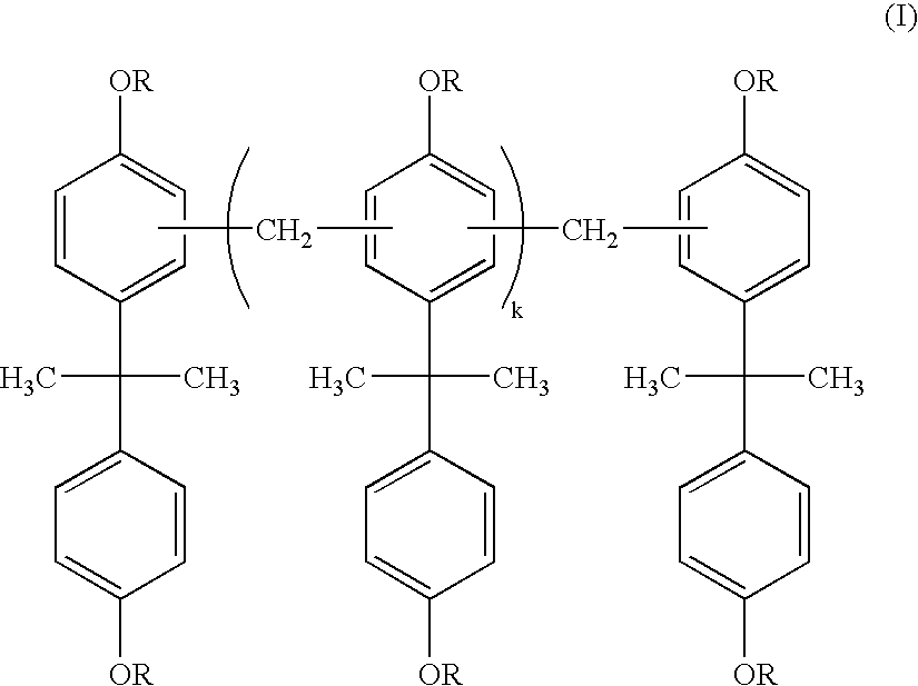
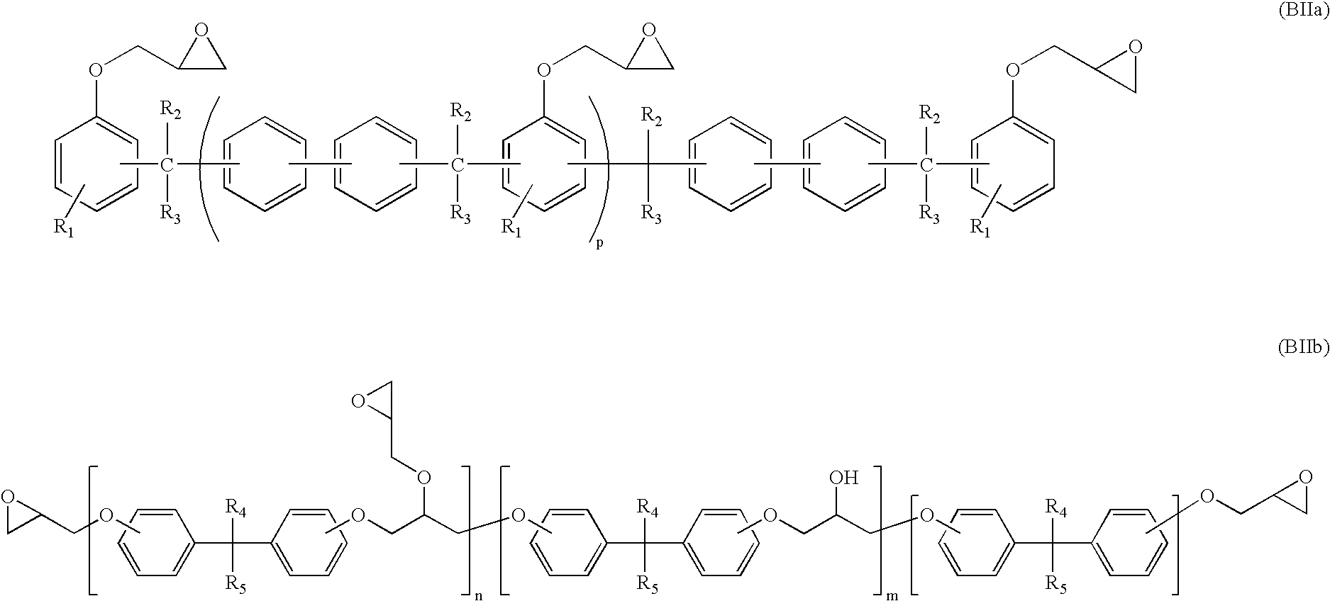
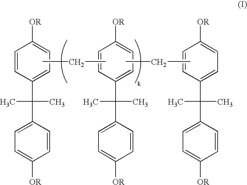
A permanent photoresist composition comprising: (A) one or more bisphenol A-novolac epoxy resins according to Formula I; wherein each group R in Formula I is individually selected from glycidyl or hydrogen and k in Formula I is a real number ranging from 0 to about 30; (B) one or more epoxy resins selected from the group represented by Formulas BIIa and BIIb; wherein each R1, R2 and R3 in Formula BIIa are independently selected from the group consisting of hydrogen or alkyl groups having 1 to 4 carbon atoms and the value of p in Formula BIIa is a real number ranging from 1 to 30; the values of n and m in Formula BIIb are independently real numbers ranging from 1 to 30 and each R4 and R5 in Formula BIIb are independently selected from hydrogen, alkyl groups having 1 to 4 carbon atoms, or trifluoromethyl; (C) one or more cationic photoinitiators (also known as photoacid generators or PAGs); and (D) one or more solvents.

Description

CROSS-REFERENCE TO RELATED APPLICATIONS [0001] This application claims the benefit of U.S. Provisional Application No. 60 / 544,403 filed Feb. 13, 2004, which is incorporated by reference in its entirety.BACKGROUND OF THE INVENTION [0002] 1. Field of the Invention [0003] This invention relates to photoimageable epoxy resin compositions and the permanent cured products thereof, that are useful in the fabrication of MEMS (micro-electromechanical system) components, micromachine components, microfluidic components, μ-TAS (micro total analytical system) components, ink-jet printer components, microreactor components, electroconductive layers, LIGA components, forms and stamps for microinjection molding and hot embossing, screens or stencils for fine printing applications, MEMS and semiconductor packaging components, BioMEMS and biophotonic devices, and printed wiring boards that can be processed by ultraviolet (UV) lithography or imprinted using hot embossing. [0004] 2. Brief Description ...

Claims


Application Information

Patent Timeline
Patent Type & Authority Applications(United States)
IPC IPC(8): C08G59/32C08G59/68G03C1/492G03F7/00G03F7/038
CPCB82Y10/00B82Y40/00C08G59/3218C08G59/687H05K3/287G03F7/001G03F7/038G03F7/0385G03F7/0002C08L63/04C08L63/00
Inventor WEBER, WILLIAMMORI, SATOSHIHONDA, NAOJOHNSON, DONALDDOCANTO, MANUEL
Owner MICROCHEM CORP
Why Eureka
Try Eureka