Smooth outer coating for combustor components and coating method therefor

a technology of combustor components and outer coatings, applied in the field of components, can solve problems such as failure to achieve cracking, and achieve the effect of reducing the incidence of cracking

Inactive Publication Date: 2005-12-22
GENERAL ELECTRIC CO
View PDF12 Cites 16 Cited by
  • Summary
  • Abstract
  • Description
  • Claims
  • Application Information

AI Technical Summary

Benefits of technology

[0005] The present invention generally provides a coating and method for reducing the incidence of cracking in a combustor assembly of a gas turbine engine. More particularly, the invention concerns combustor assemblies that comprise at least two components welded together to define a weld region, and where the weld region and regions adjacent thereto are prone to cracking at combustion temperatures sustained within the combustion chamber of the gas turbine engine.
[0007] The method of this invention also involves reducing convective and radiant heat transfer to gas turbine engine combustor assemblies that comprise at least two components welded together to define a weld region that is prone to cracking. The method entails thermal spraying a metallic bond coat on a surface of the weld region, depositing a ceramic coating on a surface of the bond coat by thermal spraying a powder having a particle size of not greater than ten micrometers, and then processing the ceramic coating to form an outer surface that is smoother than the surface of the bond coat on which the ceramic coating is deposited.
[0008] The coating system of this invention is preferably characterized by a dense ceramic coating that has sufficiently low emissivity and low thermal conductivity to be capable of thermally protecting the weld region from thermal radiation incident on the combustor assembly. Low thermal radiation absorption by the ceramic coating, preferably in combination with backside cooling of the weld region, effectively minimizes the temperature within the weld region to the degree that the incidence of cracking is reduced and the overall reliability of the combustor assembly is significantly improved.

Problems solved by technology

However, such attempts have not been successful.

Method used


Image

  • Smooth outer coating for combustor components and coating method therefor
  • Smooth outer coating for combustor components and coating method therefor
  • Smooth outer coating for combustor components and coating method therefor

Examples


Embodiment Construction

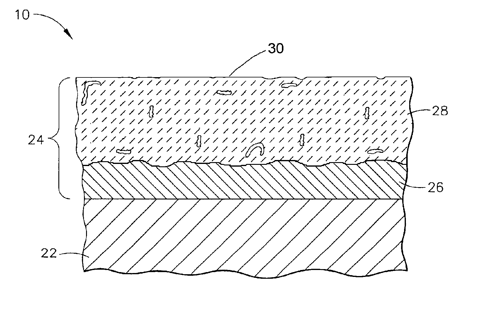
[0013] The present invention will be described in reference to a combustor 10 of an aerospace gas turbine engine depicted in FIG. 1. A portion of the combustor 10 is shown in cross-section in FIG. 1. The combustor 10 generally defines an annular-shaped combustion chamber 12 delimited by an outer liner 14, an inner liner 16, and a domed end or dome 18. FIG. 1 shows the domed 18 as including a swirl cup package 20. The combustor dome 18 is generally die-formed sheet metal attached by welding to the outer and inner liners 14 and 16. Suitable materials for the liners 14 and 16, dome 18, and the weld material include nickel, iron and cobalt-base superalloys, such as a cobalt-base alloy having a nominal composition of, by weight, about 40% cobalt, about 22% chromium, about 22% nickel, and about 14.5% tungsten. The liners 14 and 16 and dome 18 are subjected to the combustion flame and the resulting very high temperatures that exist within the combustor 10. As an apparent result of the high...


PUM

PropertyMeasurementUnit
particle sizeaaaaaaaaaa
thicknessaaaaaaaaaa
surface roughnessaaaaaaaaaa

Abstract

A coating and method for reducing the incidence of cracking in a combustor assembly of a gas turbine engine, and particularly combustor assemblies of at least two components that are welded together to define a weld region that is prone to cracking at combustion temperatures sustained within the combustion chamber of the gas turbine engine. At least the surface of the weld region protected by a coating system comprising a thermal-sprayed metallic bond coat and a ceramic coating deposited on the bond coat. The ceramic coating is deposited by thermal spraying a powder having a particle size of not greater than 10 micrometers, and the outer surface of the coating system is smoother than the outer surface of the bond coat on which the ceramic coating is deposited.

Description

CROSS REFERENCE TO RELATED APPLICATIONS [0001] This is a continuation-in-part patent application of co-pending U.S. patent application Ser. No. 10 / 710,110, filed Jun. 18, 2004.BACKGROUND OF THE INVENTION [0002] The present invention generally relates to components employed in high temperature operating environments, such as the hostile thermal environment of a gas turbine engine. More particularly, this invention relates to reducing the incidence of cracks forming in a combustor component of a gas turbine engine by applying a coating that reduces the convective and radiant heat transfer to the component. [0003] A conventional gas turbine engine of the type for aerospace applications has a combustor with an annular-shaped combustion chamber defined by inner and outer combustion liners. The upstream ends of the combustion liners are secured to an annular-shaped dome that defines the upstream end of the combustion chamber. A number of circumferentially-spaced contoured cups are formed ...

Claims


Application Information

Patent Timeline
Patent Type & Authority Applications(United States)
IPC IPC(8): B32B15/00C23C4/00C23C4/02F23M5/00F23R3/00
CPCC23C4/00C23C4/02F05B2230/90Y10T428/12771F23M2900/05004F23R3/007Y10T428/12535F23M5/00
Inventor GUPTA, BHUPENDRA KUMAREMILIANOWICZ, EDWARD JOHNMUNEERUDDIN, MOHAMED
Owner GENERAL ELECTRIC CO
Why Eureka
Try Eureka