Manufacturing methods of catalysts for carbon fiber composition and carbon material compound, manufacturing methods of carbon fiber and catalyst material for fuel cell, and catalyst material for fuel cell

a technology of carbon fiber and composition, which is applied in the direction of cell components, non-metal conductors, sustainable manufacturing/processing, etc., can solve the problems of insufficient gas diffusion, large electrode efficiency cannot be obtained, and fuel is partly wasted

Inactive Publication Date: 2006-01-05
KK TOSHIBA
View PDF6 Cites 105 Cited by
  • Summary
  • Abstract
  • Description
  • Claims
  • Application Information

AI Technical Summary

Problems solved by technology

Particulate carbon is often used as this catalyst carrier but there is such a problem that resistance is large when carbon particles are mechanically contacted and a large electrode efficiency cannot be obtained.
At the same time, there was also a problem that as the spatial configuration was not sufficient, diffusion of gas was insufficient.
Further, there was such a problem that there were catalyst particles for fuel cell between carbon particles contacting portion and less participate in reaction with fuel and fuel was partly wasted.
It is the present state, however, that in any report so far published, a technology to manufacture an electrode comprising carbon fiber carrying micro catalyst particles uniformly and high thickly has not yet been developed.
However, active carbon fiber having a large specific surface area is in a diameter as large as more than several μm and is bulky and therefore, it is difficult to apply as a carrier.
Further, VGCF carbon is a proper size in a diameter of several hundred nm, but is small in specific surface area 100 m2 / g and is not adequate to a catalyst carrier.
Further, carbon nano-tube attracting attention as a new material may have a specific surface area in some one but is as very fine as several nm˜several 10 nm, and fills up a space and not desirable.
As described above, there was no carbon fiber satisfying both of specific surface area and size and insufficient catalyst carrier was used so far.
When manufacturing fuel sells, etc., cells having sufficient output could not be manufactured.

Method used


Image

  • Manufacturing methods of catalysts for carbon fiber composition and carbon material compound, manufacturing methods of carbon fiber and catalyst material for fuel cell, and catalyst material for fuel cell
  • Manufacturing methods of catalysts for carbon fiber composition and carbon material compound, manufacturing methods of carbon fiber and catalyst material for fuel cell, and catalyst material for fuel cell
  • Manufacturing methods of catalysts for carbon fiber composition and carbon material compound, manufacturing methods of carbon fiber and catalyst material for fuel cell, and catalyst material for fuel cell

Examples


first embodiment

(Catalyst Material for First Fuel Cell)

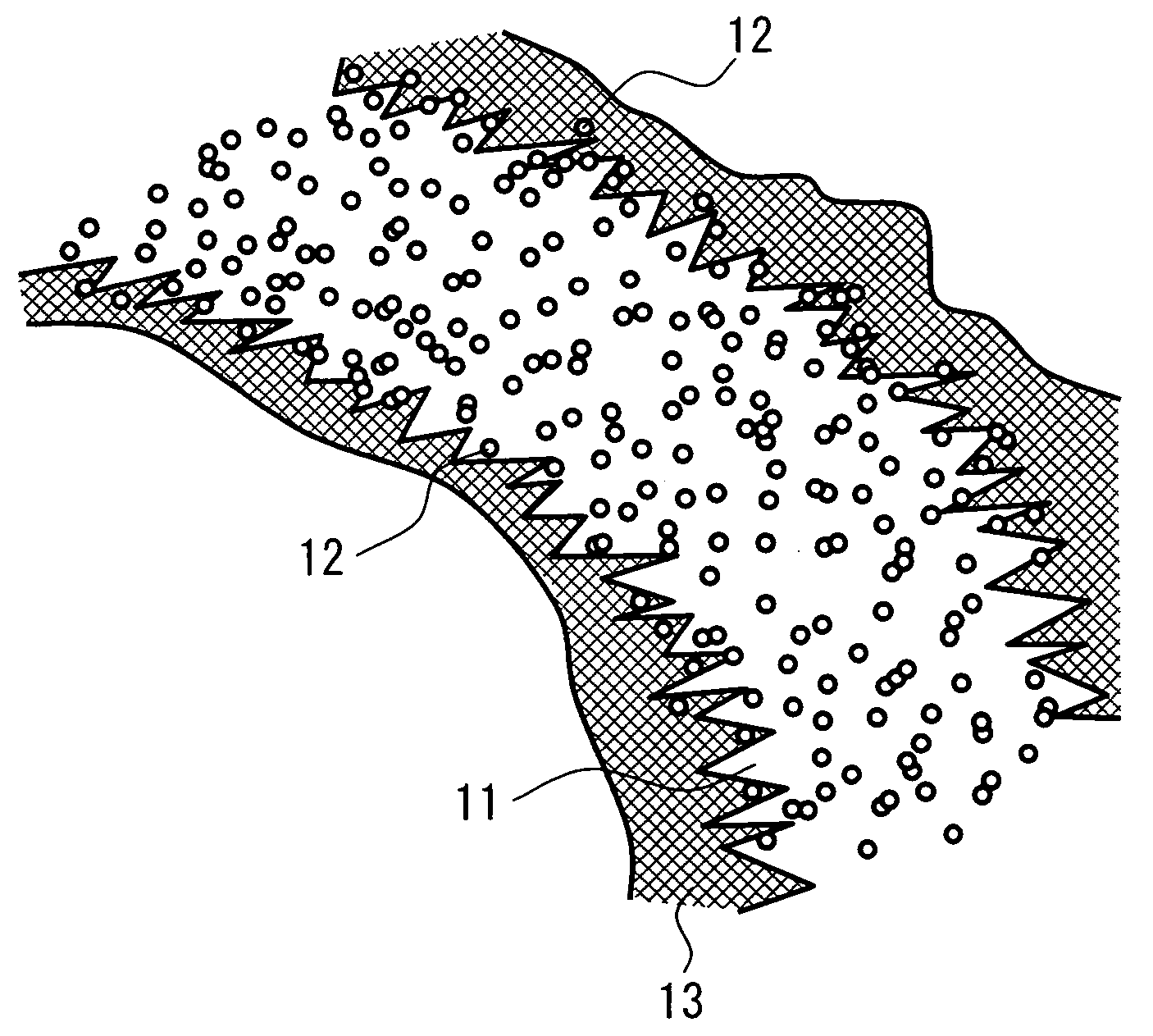
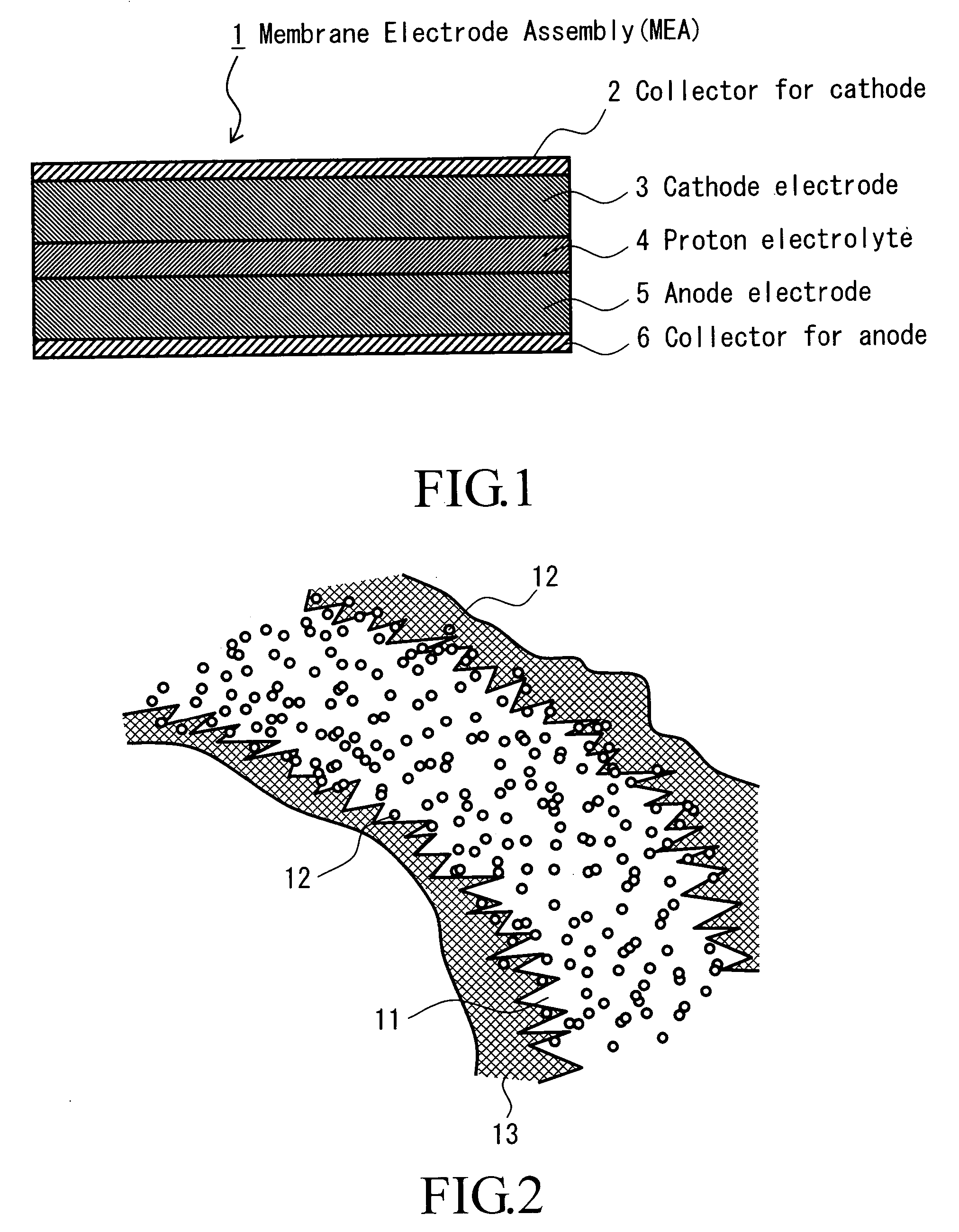
[0034] Catalyst material for the first fuel cell of the present invention is characterized in that it includes carbon fibers in a mean diameter in the range of 100˜1000 nm and a specific surface area according to BET method in the range of 200˜500 m2 / g and

[0035] Catalyst particles containing the first metallic element (catalyst metallic element for fuel cell) comprising at least one of Pt and Ru and the second metallic element (elements other than the first metallic element) of less than 30 weight %.

[0036] According to such catalyst materials, it is possible to secure an electronic conduction path by thoroughly contacting carbon fibers each other and increase catalyst carrying amount. As the result, the output characteristic of fuel cells equipped with an anode electrode containing such catalyst material or a cathode electrode containing catalyst material can be improved.

[0037] The reason for why mean diameter of carbon fiber is limited to...

second embodiment

[0306] Next, another embodiment of this invention will be explained.

[0307] For example, in a fuel cell using methanol and water as fuel, liquid fuel is supplied to an anode electrode. On the other hand, an anode electrode made of porous materials is used in order to efficiently use catalysts in the electrode.

[0308] When liquid fuel reaches he proton conductive membrane by passing through the pore in the anode electrode, liquid fuel is transmitted to the proton conductive membrane and arrives at the cathode. As a result, fuel reacts directly with oxygen supplied to the cathode electrode and the cell may not function as a cell.

[0309] This embodiment resolves the said problem and a cross-sectional view of this embodiment is shown and explained below.

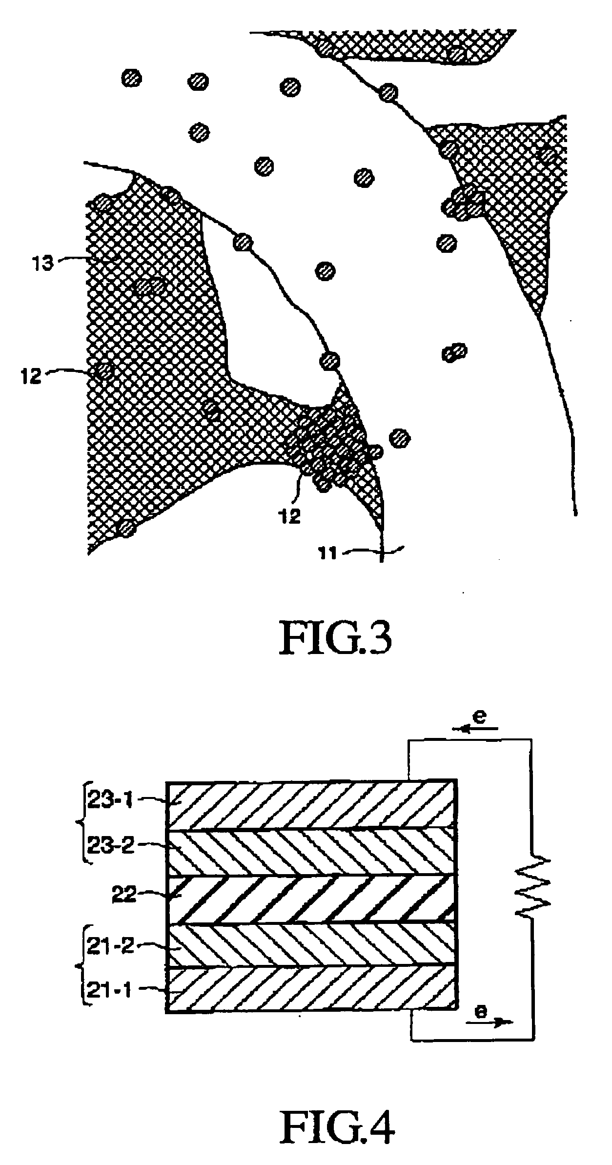
[0310] An electrode shown in FIG. 6 has a laminated catalytic layer formed on the surface of a collector 31 by sequentially laminating a catalytic layer 32 (hereinafter, called as a sparse catalytic layer) having large pores or a high p...

embodiment 1

[0329] Weighing nickel oxide in a mean particle size of primary particle 50 nm (Kojundo Chemical Laboratory: NI004PB, Purity 99.9%) and copper oxide (Kanto Kagaku made Trade Name: JIS Special Class Powder) so that the atomic ratio of Ni and Cu after reduced becomes 1:1, and mixing δ-phase alumina (Nippon Aerosil) in a mean particle size 30 nm to 5 volume % to the volume of Ni an Cu, raw material powder was manufactured.

[0330] Then, mixed power comprising 3 kinds of powders of nickel oxide, copper oxide and alumina are mixed and pulverized for 1 days using a planetary ball mill comprising a alumina ball and a container.

[0331] After mixing, put the powder in a crystal made boat and set in a tubular furnace. Then, reduce the inside of the tubular furnace by supplying a 1:1 mixed gas of hydrogen and argon mixed at 100 ml per min. and the temperature was increased by 10° C. / min. up to 200° C. and held for 10 min. Thereafter, changing the mixing rate of gas gradually to 100% hydrogen ga...


PUM

PropertyMeasurementUnit
particle sizeaaaaaaaaaa
mean primary particle sizeaaaaaaaaaa

Abstract

The carbon fibers of this invention is characterized in that irreducible inorganic material particles in a mean primary particle size below 500 nm and reducible inorganic material particles in a mean primary particle size below 500 nm were mixed by pulverizing and then, the mixture was heat treated under the reducing atmosphere and metal particles in a mean particle size below 1 μm were obtained, and the mixed powder of the thus obtained metal particles with the irreducible inorganic material particles are included in the carbon fibers.

Description

TECHNICAL FIELD [0001] The present invention relates to manufacturing a method of carbon fiber synthesizing catalysts and carbon fibers using this carbon fiber synthesizing catalyst, and a manufacturing method of fuel cell catalytic material using the carbon fiber synthesizing catalyst. PRIOR TECHNOLOGY [0002] In recent years, fuel cell is largely attracting public attentions as an electric power generating technology with less emission of carbon dioxide and less environmental burden. [0003] In the electrode of conventional fuel-cell, a film electrode complex that is an fuel-cell stack composed in a laminated layer structure comprising cathode current collector / cathode electrode (air pole) / proton electrolyte that is ion conductive material / anode electrolyte (fuel pole) / anode current corrector. In this fuel-cell, fuel gas such as hydrogen gas supplied to the anode electrode side is decomposed and ionized by a catalyst contained in the electrode and then, is moved to the cathode elect...

Claims


Application Information

Patent Timeline
Patent Type & Authority Applications(United States)
IPC IPC(8): H01M4/96H01M4/88D01F9/12H01M4/04
CPCB82Y30/00D01F9/1271H01M4/0471H01M4/8652H01M4/881H01M4/8828Y02E60/521H01M4/8892H01M4/90H01M4/9083H01M4/926H01M4/96H01M8/1004H01M4/8842Y02P70/50Y02E60/50Y02E60/10
Inventor SUENAGA, SEIICHIYONETSU, MAKITOMIMATSU, NORIHIROOOZU, HIDEYUKIGOTO, YASUHIRONAKANO, YOSHIHIKOONODERA, SHINICHI
Owner KK TOSHIBA
Why Eureka
Try Eureka