Variable attenuator

Inactive Publication Date: 2006-01-19
Q VIS
View PDF11 Cites 3 Cited by
  • Summary
  • Abstract
  • Description
  • Claims
  • Application Information

AI Technical Summary

Benefits of technology

[0008] It is a further object of the invention to provide a means to control laser fluence without affecting other parameters such as beam direction or spatial distribution to an unacceptable extent.
[0011] rotating said optical element about an axis substantially parallel to, and preferably aligned with, said path to alter the polarisation of the laser pulse relative to the said surface thereby varying the energy of said transmitted pulse.
[0015] wherein said supporting means is such that said optical element is rotatable about an axis substantially parallel to, and preferably aligned with, said path to alter the polarisation of the laser pulse relative to said surface thereby varying the energy of said transmitted pulse.
[0018] rotating said optical window element to alter the polarization of the laser pulse relative to said faces, thereby varying the energy of said transmitted pulse.
[0023] Preferably, in either or both aspects of the invention, the means supporting the optical element is a tubular member closed at one end by the optical element. Advantageously, there is a second optical element similar to the first closing the other end of the tubular member, the two elements being arranged to substantially eliminate offset of the laser pulse.

Problems solved by technology

The use of the aforementioned methods in a high energy (ie. tens of millijoules per pulse or greater) pulsed solid state laser system is impractical because of the low damage thresholds of the optical components required to implement the respective optical configurations.
Variable attenuators such as those described above that utilise coatings are also not feasible in a solid state based refractive surgery laser system, such as that described in international patent publication WO99 / 04317, as the reflectance of the coated optics are susceptible to changes in the angle of incidence.
In these arrangements, a small change in the angle of incidence can result in very high losses, a situation that would not be suitable for a medical laser system.
Dielectric mirrors (for high energy lasers) can have a small acceptance angle of <5° with a very sharp drop off in the reflectance outside this range, which also makes them unsuitable.

Method used


Image

  • Variable attenuator
  • Variable attenuator
  • Variable attenuator

Examples


first embodiment

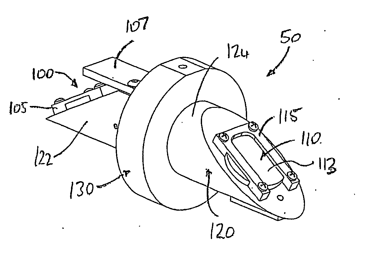
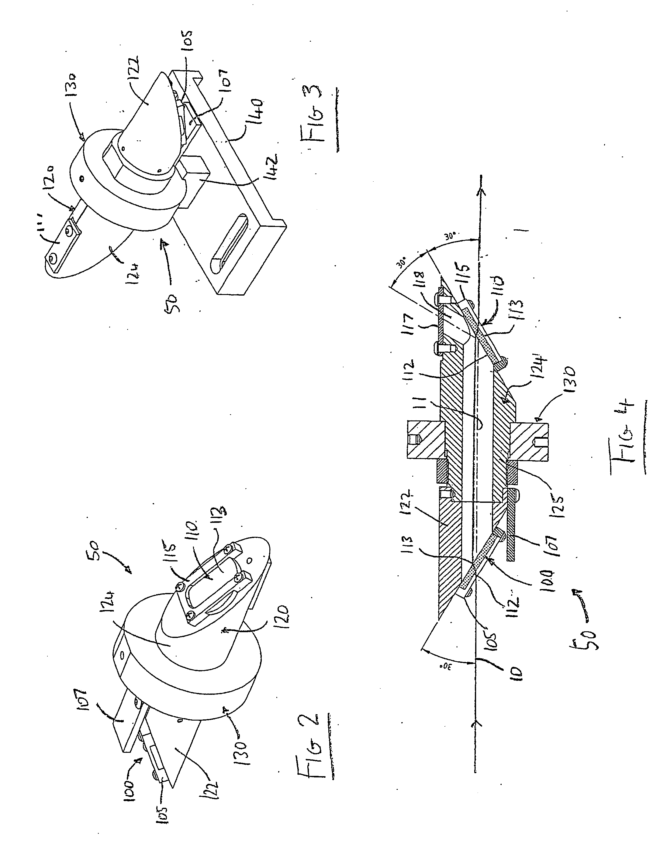
[0038] Referring to FIGS. 2 to 4, attenuator 50 consists of a pair of spaced windows 100, 110 each having parallel faces 112, 113. Windows 100, 110 are located at and close to the respective ends of a closed tube 120. The tube 120 is constructed from aluminium or another suitable material and functions purely as a mount for the windows 100&110. Tube 120 is in two interlocking parts 122, 124, one including a centre region 125, and is held in a rotator bearing 130 by a nut 132. The assembly is held via a support block 142 engaging rotator bearing 130, on a standard optical mount (shown at 140 in FIG. 3 only). In this way, the device is positioned in the laser beam delivery path so that the axis 11 of the tube is co-incident with the laser beam propagation path 10, ie. the optic axis. The assembly may have more or fewer window elements inserted depending on the amount of attenuation variability required, but will most preferably have an even number of windows.

[0039] Windows 100, 110 ar...

second embodiment

[0043] the present invention involves adjusting the windows around the axis of beam polarisation, and is depicted purely schematically in FIG. 5. In this arrangement the windows 200, 210 are not rotated around the beam incident axis, but are instead adjusted about axes 208, 209 perpendicular to the beam axis, as represented by arrows 205, 206 in FIG. 5. The two elements 200, 210 are mechanically linked to rotate synchronously but oppositely and maintain beam offset: arrows 205 indicate rotation that increases the angle of incidence and arrows 206 indicate rotation to decrease the angle of incidence. Windows 200, 210 may be supported on either side by a mounting frame (not shown) with a gear system attached to the mount.

[0044]FIG. 6 is a plot of theoretical and experimental transmittances against rotational angle of variable attenuator 50. This example illustrates the attenuation range in a 1064 nm wavelength Nd:YAG laser system. As the attenuator angle increases the 1064 nm transmit...


PUM


Abstract

Linearly polarised laser pulses are variable attenuated by rotating a plate (20) with respect to the optical axis (10). A second plate (21) may be arranged in a symmetrical manner to compensate for offset of the pulse from the optical axis (10). A feedback system may be used to control the orientation of the plates (20, 21) to achieve the desired intensity. The plates (20, 21) may comprise uncoated glass substrate, and are suitable for attenuating high energy pulses such as those used in eye surgery.

Description

FIELD OF THE INVENTION [0001] The present invention is related to the control of laser parameters, in particular energy density or fluence. BACKGROUND ART [0002] Different methods have been implemented to control the fluence of a laser system, but these methods generally include altering either pulse energy or beam diameter. One known approach is by way of a variable telescope configuration that varies the distance between a pair of lenses along the optical axis of the laser to alter the beam diameter. Another common method is to place a thin, coated optic in the path of the beam. Other attenuation and / or controlled output energy methods variously include the use of beamsplitters, linear optical absorbers, photochromatic absorbers and reflectors. [0003] Polarisation characteristics have been utilised to control energy output in a number of laser applications. U.S. Pat. No. 5,383,199 describes an arrangement for optically controlling the output energy of an UV excimer laser angioplas...

Claims


Application Information

Patent Timeline
IPC IPC(8): H01S3/10A61B18/20A61F9/01
CPCA61B18/20A61B2018/204H01S2301/04A61F2009/00872A61F9/00802
Inventor WANG, ZHENG-LIN
Owner Q VIS
Why Eureka
Try Eureka