Multi-layer polyelectrolyte membrane

a polyelectrolyte membrane and polyelectrolyte technology, applied in the direction of conductors, non-aqueous electrolyte cells, electrochemical generators, etc., can solve the problems of hydration-dehydration cycles, membranes are often subject to high differential pressure, and the technology is developed further. , to achieve the effect of reducing the size of the domain, facilitating distribution along the polymer chain, and good conductivity

Inactive Publication Date: 2006-01-19
ARKEMA INC
View PDF28 Cites 18 Cited by
  • Summary
  • Abstract
  • Description
  • Claims
  • Application Information

AI Technical Summary

Benefits of technology

[0079] One advantage of the present invention is the introduction of at least one ionic or ionizable moiety, such as a sulfonated moiety, to the polymer by copolymerization of a monomer containing the ionic or ionizable group, optionally with other monomers, in the presence of a polymer aqueous dispersion. Consequently, in the present invention, the ionic or ionizable functionality is chemically bonded to the polymer chain via polymerization thus avoiding grafting techniques.
[0080] In addition, the present invention optionally permits an intimate blending of two or more polymers in the dispersion (e.g., aqueous dispersion), preferably through the use of the seeded polymerization method or methods. Accordingly, the resulting resin can be an intimate blend of at least one polymer and at least one polymer bearing the ionic or ionizable group. Thus, the need for grafting techniques can be avoided as well as the need to use environmentally unfriendly solvent solutions. Moreover, there is no need for post-sulfonation of the resin using acids such as sulfuric and sulfonic acids or derivatives thereof, since the ionic or ionizable group, e.g., the sulfonated group, is already on the monomer. Furthermore, because the ionic or ionizable group is preferably polymerized, its distribution along the polymer chain is easily controlled by conventional means known in the art such as shot addition, continuous feed, late addition, and the like. Consequently, the resulting ionic or ionizable group distribution in a membrane formed from the polymer blend can be more easily controlled than previously. Accordingly, the tailoring of various properties, such as homogeneous, random, heterogeneous, and the like, can be achieved.
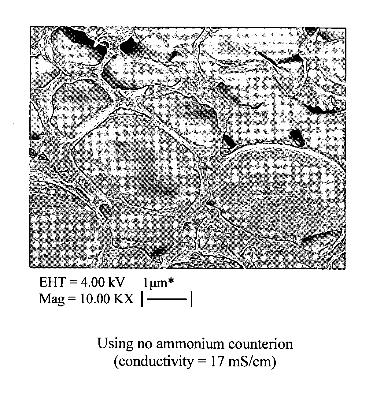
[0081] Prior to the present invention, it was believed that polymer blends containing at least one acrylic resin or vinyl resin having at least one ionic or ionizable group which had domain sizes of above 1,000 nm, when formed into a polyelectrolyte membrane layer, did not lead to good conductivity. Thus, smaller domain sizes were generally favored and developed by the present inventors. In the present invention, however, with the use of multi-layer polyelectrolyte membranes, it was discovered that the domain size of the acrylic resin or vinyl resin can be large or small and present in one or more layers. The further development of the multi-layer polyelectrolyte membrane of the present invention overcomes this previously thought problem. With the present invention, any domain size for the acrylic resin or vinyl resin can be used in one or more layers that form the multi-layer polyelectrolyte membrane. Generally, when the polymer blend containing the at least one acrylic resin or vinyl resin having at least one ionic or ionizable group is blended with at least one polymer, such as a thermoplastic fluoropolymer, domain sizes of about 1,000 nm or higher are obtained. In the present invention, the domain sizes of the acrylic resin or vinyl resin in the additional polymer can be such that the domain sizes are less than 1,000 nm, such as 700 nm to 1000 nm, 500 nm or less and in many cases significantly below 100 nm to the point where the domains are barely detectable, if detectable at all, such as shown in FIG. 2.
[0083] With respect to the ammonium compound, the ammonium compound preferably, as described above, forms a counterion to the ionic or ionizable group. This counterion is considered an ammonium counterion and more preferably an alkyl ammonium counterion and even more preferably an alkyl quaternary ammonium counterion. Preferably, the alkyl groups of the ammonium counterion are C1-C6 alkyl group though other alkyl ammoniums can be used. In addition, more than one different type of counterion can be formed such as two or more different types of ammonium counterions. The same is true for the phosphonium counterions. This can be accomplished by using two or more different ammonium and / or phosphonium materials to form different ions or a mixture of various ions.
[0084] As stated above, and strictly as an example, the sulfonated or phosphonated resins in either acid or salt form can be mixed with the ammonium compound (e.g., salt), such as an organic quaternary ammonium compound to thereby convert the resin to an ammonium salt. This step can be repeated several times to achieve satisfactory conversion of the resin to the ammonium salt. Examples of suitable ammonium salts include: tetramethylammmonium, tetraethylammonium, tetrapropylammonium, tetrabutylammonium, tetrapentylammonium, tetrahexylammonium, benzyltrimethylammonium, benzyltriethylammonium, hexamethonium, decamethonium, cetyltrimethylammonium, decyltrimethylammonium, dodecyltrimethylammonium, and methyltributylammonium. Preferably the ammonium salt has a molecular weight of at least 186. Mixtures of the ammonium salts can be utilized in the process. The ammonium can contain organic groups in a quaternary ammonium salt of the formula N R1R2R3R4+, wherein R1-R4 are independently selected from C1-C30 alkyl, aryl, aralkyl or cycloalkyl groups. The phosphonium analogs of the ammonium salts can also be used, such as tetraalkyl phosphonium salts and like.

Problems solved by technology

However, reports and literature describe these membranes as working well but show several limitations that prevent developing the technology further to commercialization.
Additionally, they work better with gaseous fuels than with liquid fuels which may be mainly due to liquid fuel crossover that diminishes cell performance.
Indeed, the membrane is often subjected to high differential pressure, hydration-dehydration cycles, as well as other stressful conditions.
Currently, many fluorine-containing membranes can suffer from one or more of the following short comings: i) high liquid and gas crossover through the membrane; ii) heterogeneous blending between the fluorinated polymer and other polymers that leads to inferior properties; iii) insufficient chemical resistance in the presence of some liquid fuels; iv) poor electrochemical resistance; v) lack of heterogeneous distribution of sulfonated groups; vi) poor mechanical properties; and / or vii) poor thermal stability.
It is known from the literature that Nafion® type polymers can have mechanical failure in methanol fuel cells as well as problems with liquid crossover.
However, the polymer blending process described does not provide an acceptable blend and the sulfonation steps are complicated.
However, such types of products have not been described for application as membranes for polyelectrolyte membranes and the like.

Method used


Image

  • Multi-layer polyelectrolyte membrane
  • Multi-layer polyelectrolyte membrane
  • Multi-layer polyelectrolyte membrane

Examples


example 1

[0136] An ionomer solution in NMP (25% by weight) of SEM / HEMAMMA / Styrene (10.8 g) (EW=278), 2.75 g of a 55% water solution of TBAOH (available from Sachem) and 40.31 g of NMP were added with mixing to a reactor vessel equipped with appropriate inlets and equipment. To 20.16 g of this solution, 2.36 g of Kynar 2801 (ATOFINA Chemicals) powder were added while stirring at 60° C. until dissolution. Once a homogeneous solution was obtained, 0.52 g of Desmodur BL3175A isocyanate cross-linker (Bayer) and 0.02 g of DBTDL catalyst are added with mixing. The solution was poured on a glass plate, spread with a doctor knife and baked for 7 minutes at 177° C. The film membrane was protonated by treatments with one molar hydrochloric (HCl) and sulfuric (H2SO4) acids for 2 hours each at 65° C., then rinsed with deionized water. The proton conductivity of the membrane, measured by AC impedance, was 30 mS / cm and the areal resistance at 25° C. is 0.15 Ω / cm2.

examples 2-7

[0137] Same preparation procedure as Example 1 above. Amounts of reactants and testing results presented in Tables 3, 4 and 5.

example 8

[0138] A NMP solution of polyelectrolyte in TBA form was prepared as follows: to 6428 g of a 25 wt % solution of polyelectrolyte in NMP, 2204 g TBAOH (55% in water) were added and the water removed. Then 4445 g NMP were added. To 6051 g of this solution were added 1878 g Kynar 2801 and 7149 g of NMP and stirred until dissolution. To 41.05 g of the polyelectrolyte / Kynar solution in NMP described above, 0.39 g of Desmodur N3300 isocyanate cross-linker (Bayer) were added with mixing. The solution was poured on a glass plate, spread with a doctor knife and baked for 7 minutes at 177° C. The membrane was protonated by treatments with one molar hydrochloric (HCl) and sulfuric (H2SO4) acids for 2 hours each at 65° C., then rinsed with deionized water. The proton conductivity of the membrane, measured by AC impedance, was 60 mS / cm and the areal resistance at 25° C. is 0.06 Ω / cm2.


PUM

PropertyMeasurementUnit
domain sizesaaaaaaaaaa
conductivityaaaaaaaaaa

Abstract

Multi-layer polyelectrolyte membranes are described wherein at least one of the layers contains at least one acrylic resin or vinyl resin having at least one ionic or ionizable group, and at least one additional polymer. The polymer has small or large domain sizes with respect to the acrylic resin or vinyl resin that is present in one or more layers. The polymer preferably has improved conductivity when formed into a film. The membranes are useful in batteries, fuel cells, and the like.

Description

BACKGROUND OF THE INVENTION [0001] The present invention relates to multi-layer polyelectrolyte membranes containing polymeric resins, for instance and more specifically to fluoropolymer and non-perfluorinated polymeric resins containing ionic and / or ionizable groups (also referred to as a “polyelectrolyte”), which are useful in a variety of products such as fuel cells and the like. The present invention further relates to methods of making these multi-layer polyelectrolyte membranes. [0002] Perfluorocarbon ionic exchange membranes provide high cation transport, and have been extensively used as ionic exchange membranes. Polymeric ion exchange membranes can be referred to as solid polymer electrolytes or polymer exchange membranes (PEM). Because of the severe requirements for fuel cell applications, the most commonly used membranes, and commercially available, are made from perfluorosulfonated Nafion®, Flemion® and Aciplex® polymers. However, reports and literature describe these me...

Claims


Application Information

Patent Timeline
Patent Type & Authority Applications(United States)
IPC IPC(8): H01M8/10H01M10/40H01M10/0565
CPCH01B1/122H01M6/181H01M8/0291Y02E60/523H01M10/0565H01M2300/0082H01M8/1004H01M8/0289Y02E60/10Y02E60/50H01M8/02H01M8/10
Inventor HEDHLI, LOTFIDECKER, ISABELLEPICCIONE, PATRICK M.AMORT, HOLGERGABOURY, SCOTT R.PIROUX, FABIENNE
Owner ARKEMA INC
Why Eureka
Try Eureka