Device and method for milling of material using ions

a technology of ions and milling devices, which is applied in the direction of discharge tube/lamp details, material analysis using wave/particle radiation, nuclear engineering, etc., can solve the problems of adversely affecting the quality of the specimen image, the inability of higher current milling to maintain a small beam diameter, and the inability to develop higher energies with appropriate current, etc., to achieve the effect of reducing the amount of sputtered material, promoting the ability to raster the beam, and small beam spo

Active Publication Date: 2006-02-02
E A FISCHIONE INSTR
View PDF3 Cites 25 Cited by
  • Summary
  • Abstract
  • Description
  • Claims
  • Application Information

AI Technical Summary

Benefits of technology

[0009] An ion mill is described which provides the capability of preparing a specimen utilizing a variety of low and high ion beam energies, while maintaining a relatively small beam spot size or diameter. The use of a small beam spot size minimizes the amount of sputtered material which may b...

Problems solved by technology

Conventional ion milling has been accomplished utilizing lower energy devices, typically in the 50-100 eV range, but devices designed for this low energy utilization are frequently incapable of developing higher energies with appropriate current.
Additionally, devices capable of higher energy, higher current milling cannot maintain a small beam diameter.
One problem with focused ion beam etching as used in TEM specimen preparation is, because of the high ion energy and/or mass, the FIB processes often damage the crystalline structure of the specimen, thereby causing amorphization.
Amorphization and implantation both adversely affect the quality of the TEM image that may be obtained from the specimen.
This problem, known as redeposition, also adversely affects the quality of the TEM image obtained from the specimen.
In any of the previous examples of specimen preparation, the use of mechanical grinding and cutting techniques,...

Method used


Image

  • Device and method for milling of material using ions
  • Device and method for milling of material using ions
  • Device and method for milling of material using ions

Examples


Embodiment Construction

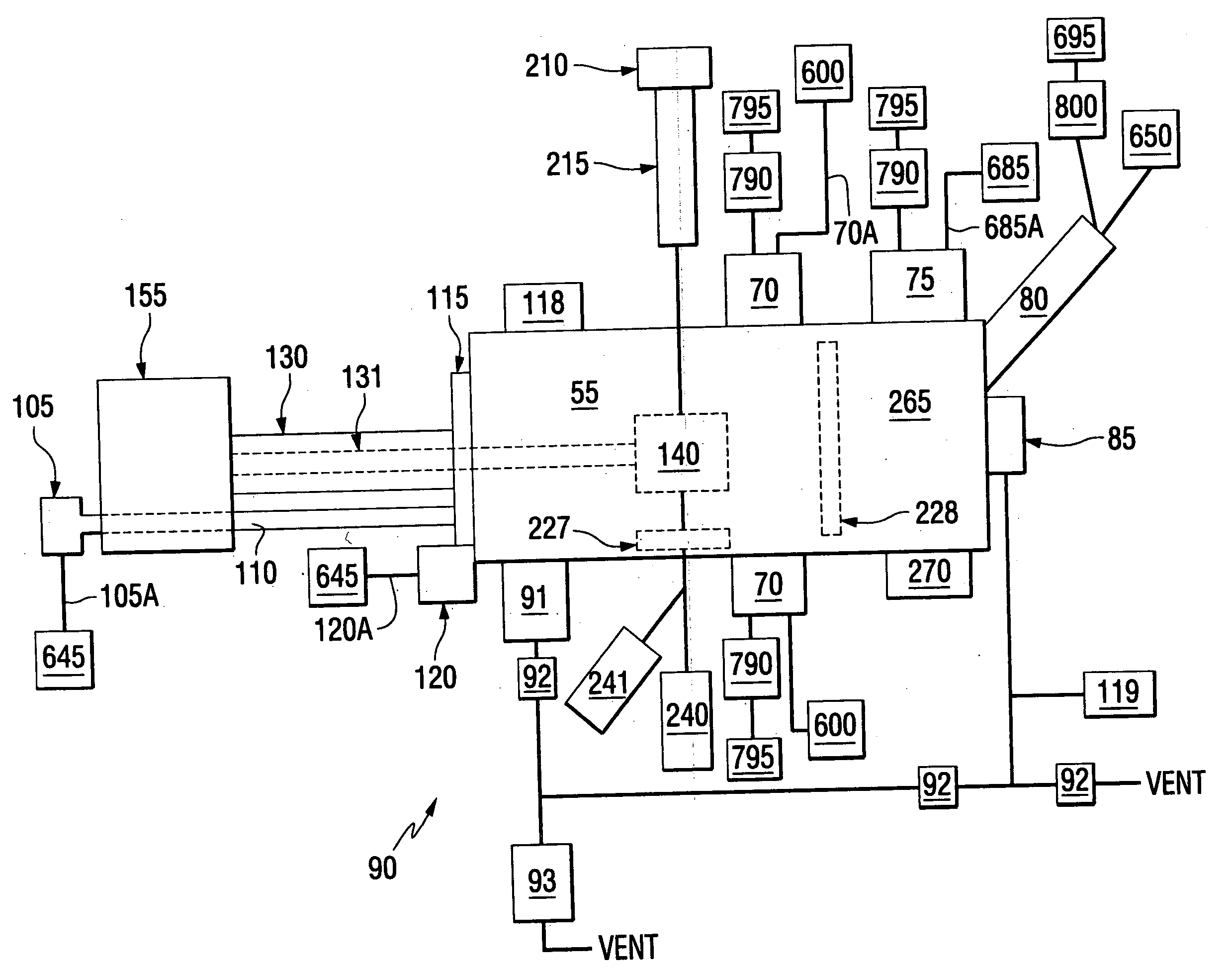
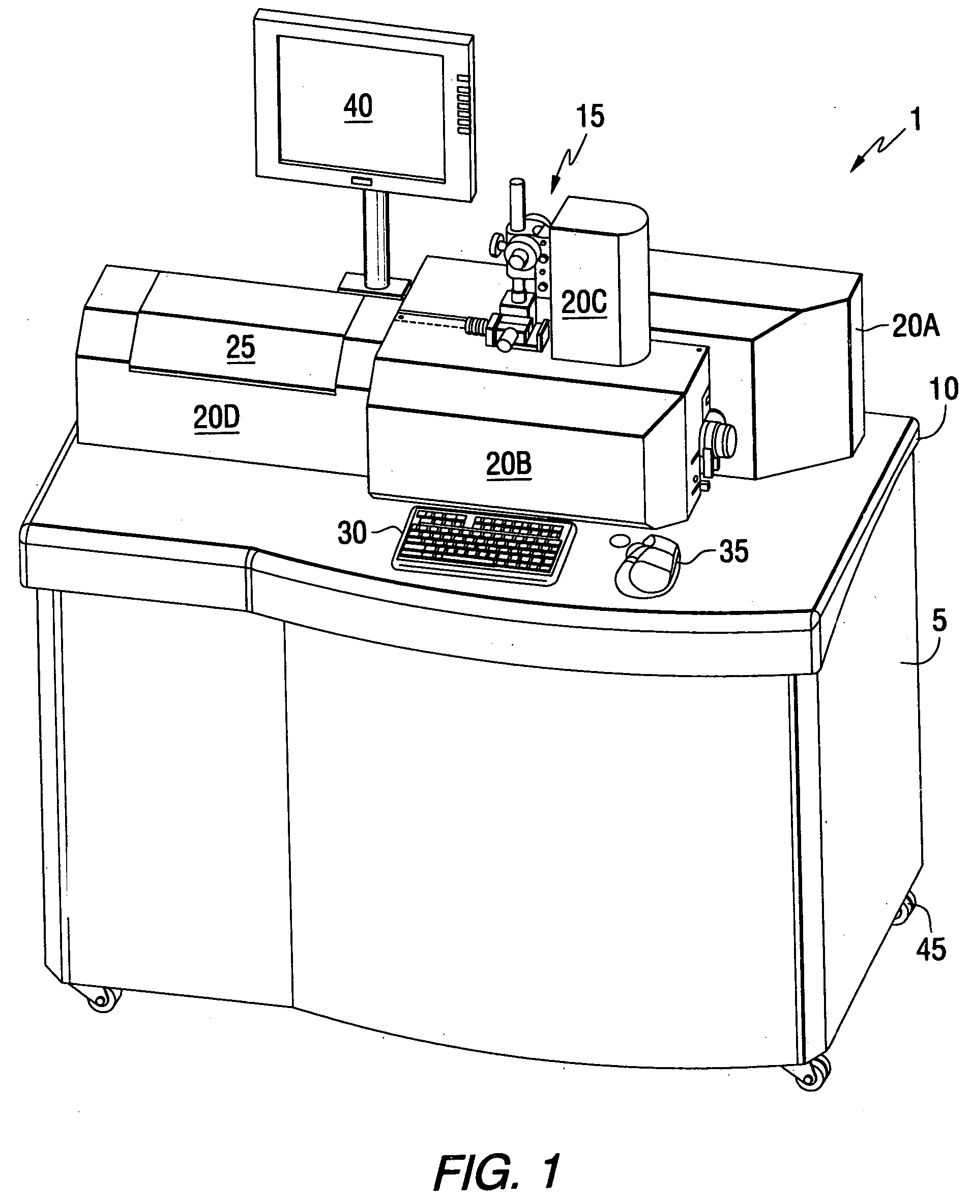
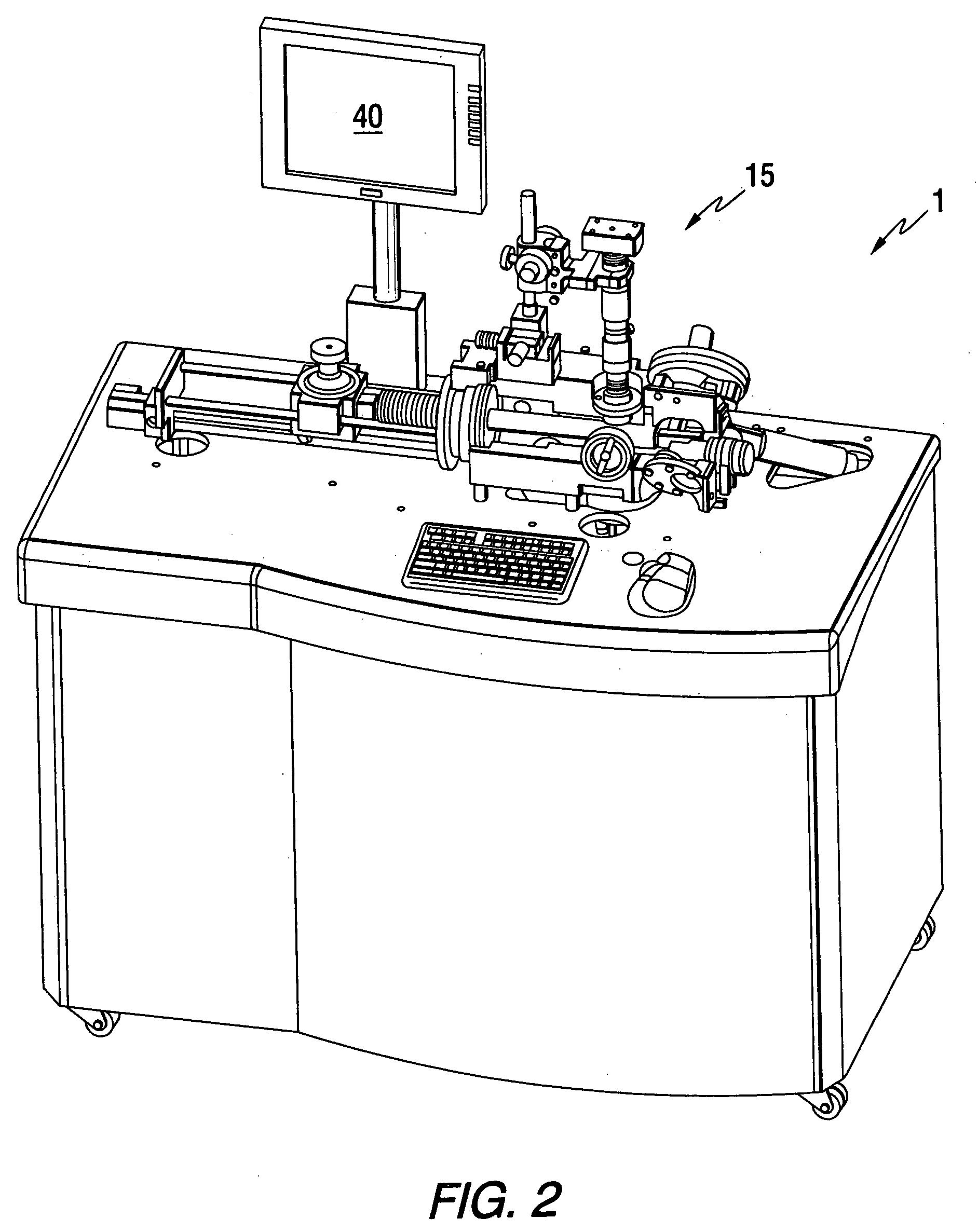
[0045] Referring now to FIGS. 1 and 2, an ion mill 1 is shown having a base cabinet 5, which is utilized to support the operable equipment and to enclose the power supply, vacuum system and circuitry utilized in the device. Base cabinet 5 includes a plurality of removable or openable panels to provide access to the internal components and storage spaces. The cabinet includes a counter top 10, which is made of an inert and durable material, which will withstand both physical and chemical abuse or attack while in use in a laboratory setting. In operation, the combined milling mechanism 15 is provided with covers 20A through 20D, which are utilized to provide both an aesthetically pleasing exterior surface, as well as protection for the relatively delicate device components. Each of the covers 20A through 20D provides removable access to these components for repair or inspection. A dewar access panel 25 is provided as a readily openable or removable cover to permit easy access to the i...


PUM

PropertyMeasurementUnit
Angleaaaaaaaaaa
Angleaaaaaaaaaa
Angleaaaaaaaaaa

Abstract

A milling device is disclosed for the preparation of microscopy specimens or other surface science applications through the use of ion bombardment. The device provides the ability to utilize both gross and fine modification of the specimen surface through the use of high and low energy ion sources. Precise control of the location of the specimen within the impingement beams created by the ion sources provides the ability to tilt and rotate the specimen with respect thereto. Locational control also permits the translocation of the specimen between the various sources under programmatic control and under consistent vacuum conditions. A load lock mechanism is also provided to permit the introduction of specimens into the device without loss of vacuum and with the ability to return the specimen to ambient temperature during such load and unload operation. The specimen may be observed and imaged during all active phases of operation.

Description

FIELD OF THE INVENTION [0001] The present invention relates to an apparatus for the controlled removal of material from surface science technology or electron microscopy specimens as part of a specimen preparation technique. More specifically, the invention relates to a device including both high and low energy ion milling capabilities within a closely controlled environment, including, but not limited to, the parameters of specimen temperature, specimen location and vacuum. The invention further relates to a method for utilizing the disclosed device for the preparation of surface science technology or electron microscopy specimens. BACKGROUND OF THE INVENTION [0002] A charged particle instrument uses electrons that interact with a specimen to gain information from the specimen. Examples of such instruments are transmission electron microscope, atomic force microscopes, atom probe field ion microscopes and devices incorporating other scanned probe and x-ray technology for high magni...

Claims


Application Information

Patent Timeline
IPC IPC(8): H01J37/08
CPCH01J37/08H01J37/20H01J37/22H01J37/244H01J2237/31745H01J37/305H01J2237/0822H01J2237/30477H01J2237/3174H01J37/3002
Inventor FISCHIONE, PAUL E.SMITH, DAVID W.SCHEINFEIN, MICHAEL R.MATESA, JOSEPH M.SWIHART, THOMAS C.MARTIN, DAVID
Owner E A FISCHIONE INSTR
Why Eureka
Try Eureka