Feedthrough capacitor filter assemblies with laminar flow delaminations for helium leak detection

Inactive Publication Date: 2006-02-02
WILSON GREATBATCH LTD
View PDF12 Cites 12 Cited by
  • Summary
  • Abstract
  • Description
  • Claims
  • Application Information

AI Technical Summary

Benefits of technology

[0012] In accordance with the invention, an improved electromagnetic interference (EMI) feedthrough filter assembly for use in an active implantable medical device (AIMD) is provided. The assembly comprises a capacitor having first and second sets of electrode plates embedded within a dielectric body such as a monolithic ceramic material. A conductive ferrule is conductively coupled to the second set of electro

Problems solved by technology

Unfortunately, these lead wires can act as an antenna to collect stray electromagnetic interference (EMI) signals for transmission via the terminal pins into the interior of the medical device.
Such unwanted EMI signals can disrupt proper operation of the medical device, resulting in malfunction or failure.
For example, it has been documented that stray EMI signals emanating from cellular telephones can inhibit pacemaker operation, resulting in asynchronous pacing, tracking and missed beats.
More particularly, a defective braze or a defective glass-based seal structure, which would permit undesirable leakage of patient body fluids when mounted on a medical device and implanted into a patient, can be obstructed by the mounting of the filter capacitor and its associated electromechanical connections.
While the bulk permeability of the epoxy material is such that helium under pressure can penetrate therethrough in the presence of a defective hermetic seal, the duration of this pressure test (typically a few seconds) is often insufficient to permit such penetration.
The thus-tested feedthrough assembly can then mistakenly be incorporated into a medical device and impl

Method used


Image

  • Feedthrough capacitor filter assemblies with laminar flow delaminations for helium leak detection
  • Feedthrough capacitor filter assemblies with laminar flow delaminations for helium leak detection
  • Feedthrough capacitor filter assemblies with laminar flow delaminations for helium leak detection

Examples


Embodiment Construction

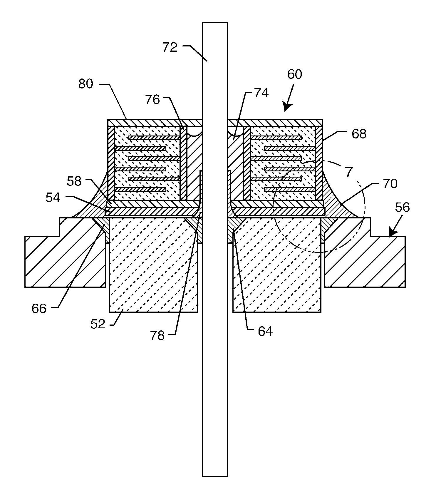
[0027] An improved feedthrough capacitor filter assembly is provided for use in active implantable medical devices (AIMDs) and the like, such as in a cardiac pacemaker, a cardiac sensing system, a neurostimulator, a cochlear implant, a deep brain stimulator, an implantable defibrillator, a congestive heart failure device, a hearing implant, a drug pump, a ventricular assist device, an insulin pump, a spinal cord stimulator, an artificial heart, an incontinence device, a bone growth stimulator, a gastric pacemaker, or a prosthetic device. This improved filter assembly includes a laminar delamination gap for facilitated hermetic seal testing subsequent to manufacture and prior to use.

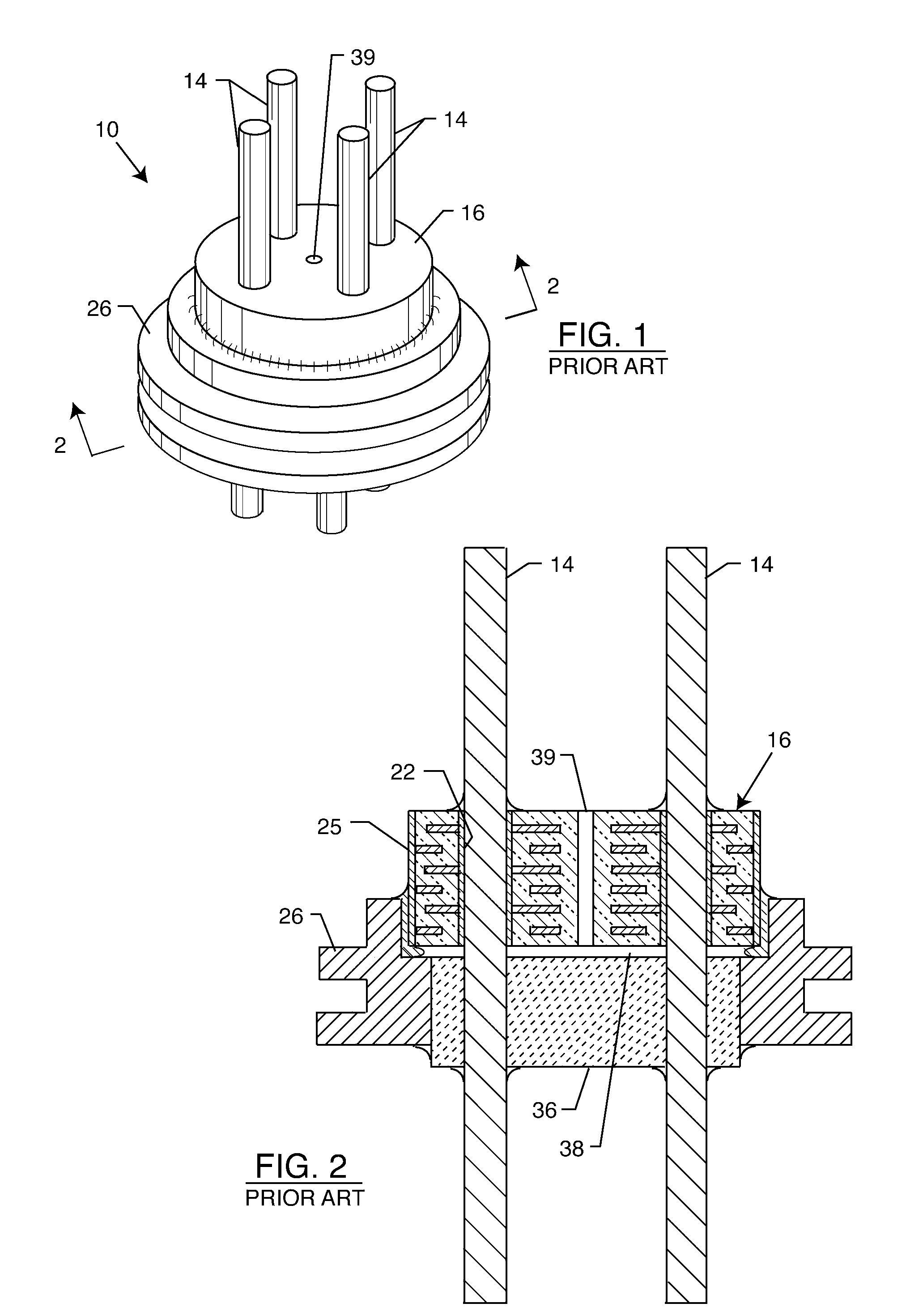
[0028]FIGS. 1 and 2, taken from FIGS. 1 and 2 of U.S. Pat. No. 6,566,978, depict a variation on a feedthrough filter assembly 10 with a leak detection vent 39 from the prior art. In this prior art form, the feedthrough filter assembly 10 comprises a capacitor body 16, at least one terminal pin 14 extendi...


PUM


Abstract

A feedthrough filter capacitor assembly includes a capacitor having first and second sets of conductive electrode plates embedded within a dielectric body and mounted to the hermetic terminal of an implantable medical device. A laminar delamination gap is provided between the capacitor sealing materials and the hermetic terminal assembly to facilitate helium leak detection. At least one feedthrough terminal pin extends through the capacitor in conductive relation with the first set of electrode plates, and an outer ferrule is mounted about the capacitor in conductive relation with the second set of electrode plates. The mounting washer is spaced against the hermetic seal and is adhesively connected to the feedthrough capacitor. The mounting washer forms a laminar flow delamination through which helium molecules can flow during a helium leak detection test. Provision is made for a pre-connection to the gold braze so that the capacitor inside diameter termination is not electrically isolated from the lead wire.

Description

BACKGROUND OF THE INVENTION [0001] This invention relates generally to feedthrough capacitor filter assemblies, particularly of the type used in implantable medical devices such as cardiac pacemakers, cardioverter defibrillators and the like, to decouple and shield internal electronic components of the medical device from undesirable electromagnetic interference (EMI) signals. More specifically, this invention relates to an improved feedthrough capacitor filter assembly of the type incorporating a hermetic seal to prevent passage or leakage of fluids through the filter assembly, wherein a laminar flow delamination is provided to accommodate and facilitate post manufacture and pre-usage testing of the hermetic seal. [0002] Feedthrough terminal pin assemblies are generally well known in the art for use in connecting electrical signals through the housing or case of an electronic instrument. For example, in implantable medical devices such as cardiac pacemakers, defibrillators and the ...

Claims


Application Information

Patent Timeline
IPC IPC(8): H01G4/35
CPCH01G4/35A61N1/3754
Inventor BRENDEL, RICHARD L.
Owner WILSON GREATBATCH LTD
Why Eureka
Try Eureka