

Device for shaping infarcted heart tissue and method of using the device
- Summary
- Abstract
- Description
- Claims
- Application Information
AI Technical Summary
Benefits of technology
Problems solved by technology
Method used
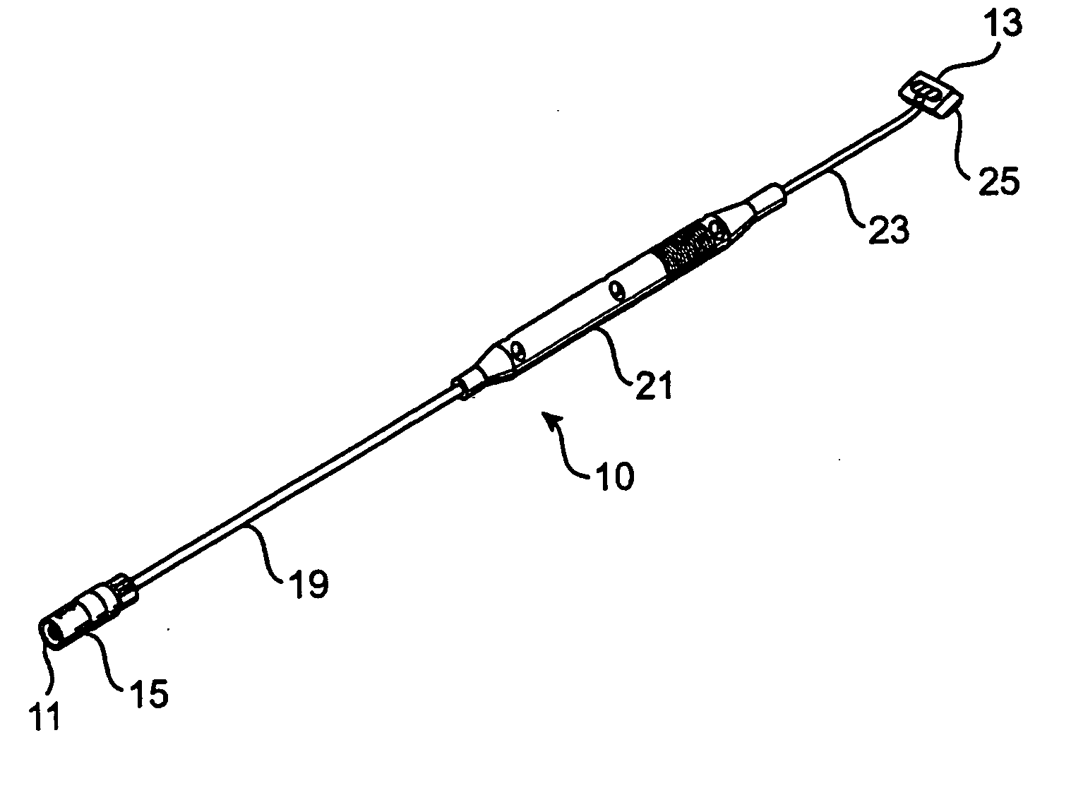
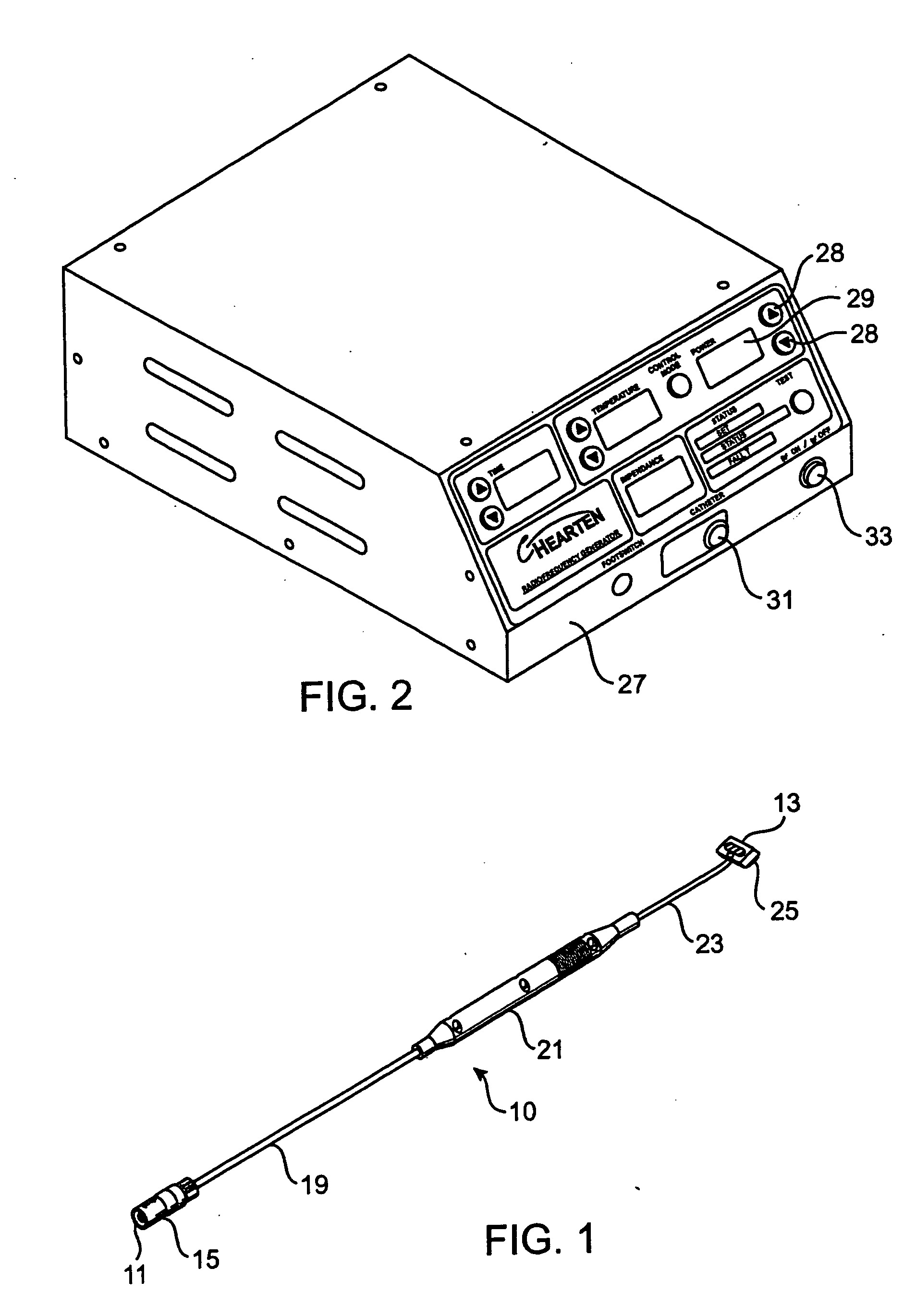
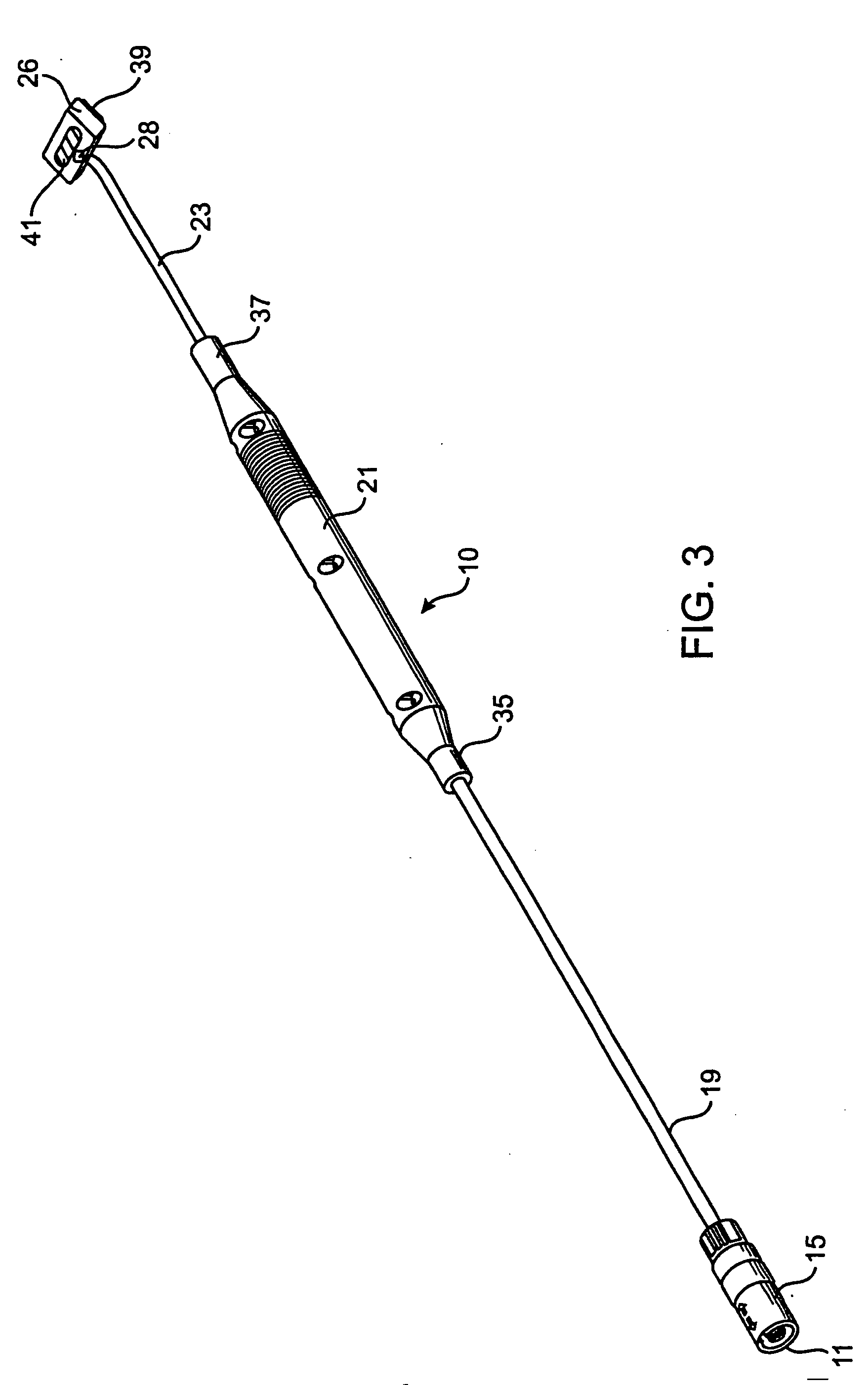
Image

Examples
example 1
[0069] Adult female Sprague-Dawley rats are anesthetized, intubated, ventilated, and the chest incised. The left main coronary artery is visualized and ligated. The chest and skin is closed. This procedure created a large myocardial infarction over the left ventricle of the heart.
[0070] After 6 weeks, the rats received echocardiography to determine the extent of the infarcted area, to measure the diastolic area, measure the systolic area, and to measure the fractional shortening of the heart (Fractional shortening is similar to ejection fraction, however ejection fraction measure the volume of blood ejected during each stroke and the fractional shortening measures the change in linear distance between the walls of the left ventricle. Fractional shortening is used in many animal experiments to assess cardiac function.)
[0071] The rats are then anesthetized, intubated, and ventilated and the chest opened. The infarct scar is visualized and sutures are placed around the infarct scar. ...
example 2
[0074] Adult female Sheep are anesthetized, intubated, ventilated, and the chest incised. The left descending coronary artery is visualized and ligated about ⅓ up from the apex to the base of the heart. Diagonal branches are also ligated about ⅓ up from the apex to the base of the heart. The chest and skin is closed. This procedure created a large myocardial infarction over the left ventricle at the apex of the heart.
[0075] After about 12 weeks, the sheep received echocardiography to determine the extent of the infarcted area, to measure the diastolic volume, measure the systolic volume, and to measure the ejection fraction heart.
[0076] The sheep are then anesthetized, intubated, and ventilated and the chest opened. The infarct scar is visualized and piezo-electric crystals are placed around the infarct scar. The crystals are from Sonometrics Corporation London Canada and a Digital Sonomicrometer from the same company is used to analyze the distances between the crystals. A heatin...
PUM
 Abstract
Description
Claims
Application Information