Liquid handling for filtration and preparative chromatography

a technology of liquid handling and chromatography, applied in the direction of filtration separation, multi-stage water/sewage treatment, separation process, etc., can solve the problems of clogging of filtration devices, affecting the efficiency of filtration devices, so as to reduce the pressure and enhance efficiency , the effect of minimal operator involvemen

Active Publication Date: 2006-02-09
PARKER INTANGIBLES LLC
View PDF20 Cites 36 Cited by
  • Summary
  • Abstract
  • Description
  • Claims
  • Application Information

AI Technical Summary

Benefits of technology

[0015] The system and process of the present invention address problems such as those noted herein by controlling operation of a liquid-moving pump unit, such as by entering pressure and/or pump rate changes with operator-defined conditions and/or parameters. The changes can be tailored for the particular liquid being handled and for the objectives of the procedure being carried out. With methods and systems as described herein, any of DFF, TFF and column loading can be carried out by cons

Problems solved by technology

However, only a relatively small amount of permeate is collected during each retentate volume-pass, and thus a significant processing time is typically associated with TFF procedures.
However, filtration devices tend to clog when used over an extended period of time and must be timely replaced.
Clogging of a filtration device occurs: (1) when the membrane pores become obstructed, typically with trapped cells, particulate matter, cell debris or the like or (2) when the feed channel (into a TFF device) becomes obstructed by solids or colloidal material and/or cell debris.
This clogging of the feed channel or membrane pores results in a decreased liquid flow across the porous filter membrane.
The result is a change in system pressure which, if not properly addressed, runs the risk of serious detriment to the operation which incorporates the filtration procedure.
At times, it is not possible to accurately predict the time at which the pumping action must be stopped in order to avoid overtaxing the filter device.
Accordingly, prior art systems which rely solely on timing are not entirely satisfactory.
Prior art filtration technology such as that referred to above also is disadvantageous because it is typically very labor intensive.
One shortcoming is that the filtrate yield frequently is no

Method used


Image

  • Liquid handling for filtration and preparative chromatography
  • Liquid handling for filtration and preparative chromatography
  • Liquid handling for filtration and preparative chromatography

Examples


example 1

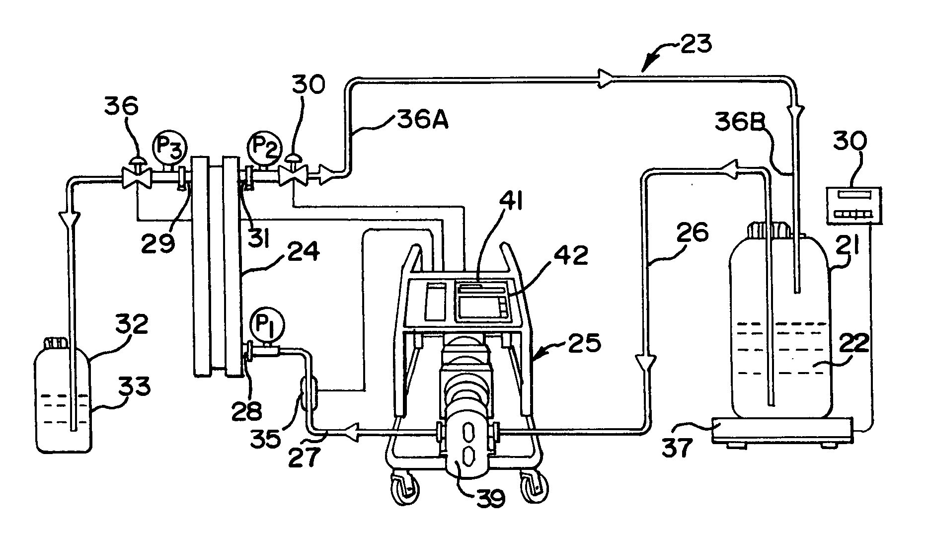
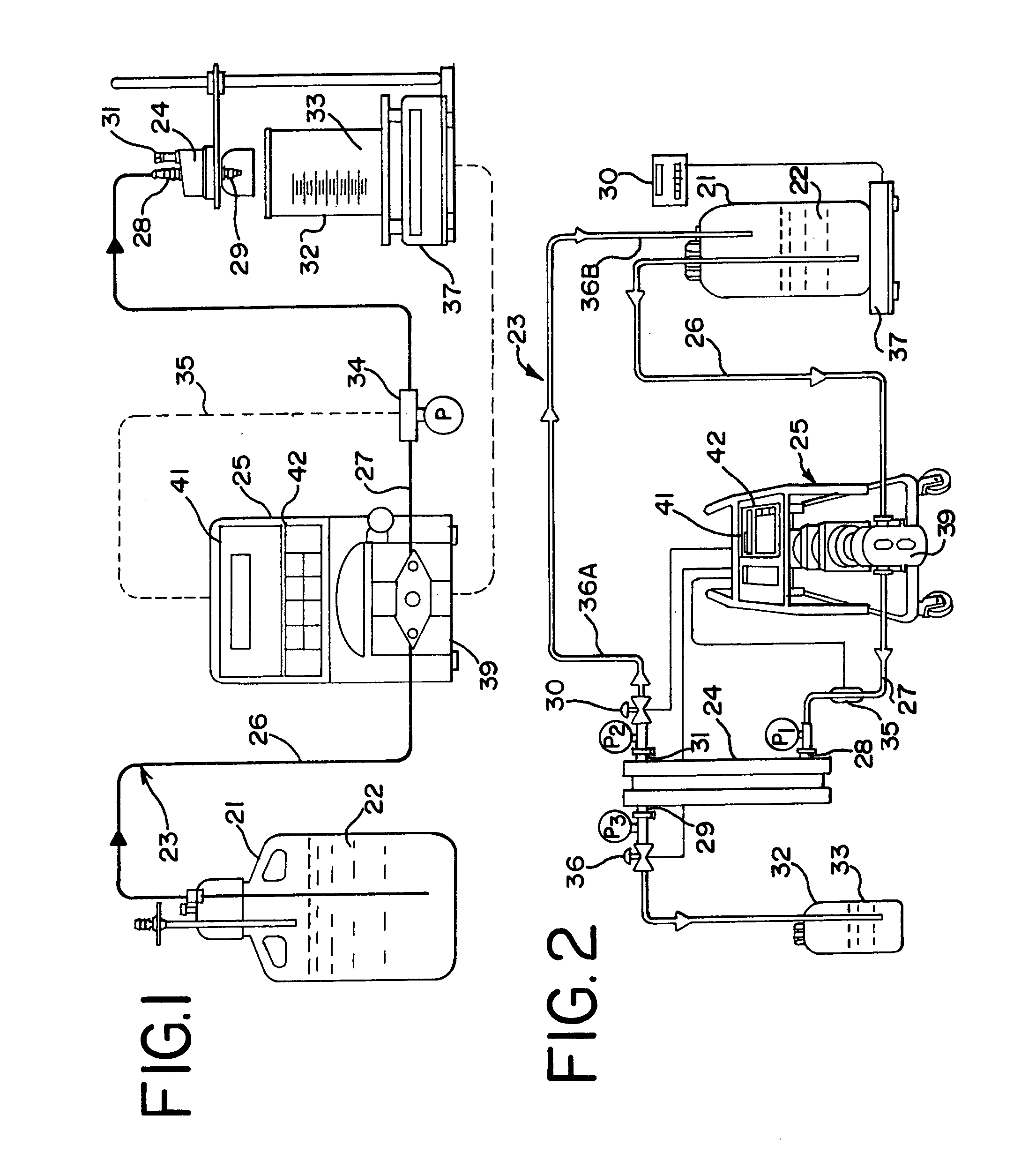
[0086] In the bioprocessing industry, solutions are filtered by DFF using either constant pressure or constant flow rate. For a given bioprocess solution, the standard procedure for determining (DFF) filter capacity involves the use of pressurized SS containers. The pressurized (20 psi) SS vessel containing the bioprocess solution replaces the pump and reservoir shown in FIG. 1. A fluid line with shutoff valve connects the pressurized vessel with the DFF device to be tested. The test procedure starts with the opening of the manual shut-off valve. The filtrate quantity is measured with an electronic scale; filtration data is collected at regular time intervals.

[0087] The standard test procedure outlined above was used to generate comparative baseline data generally as follows. A 4-liter SS container was filled with 1.0 liter of a surrogate protein solution, consisting of skimmed, fat-free milk (9 grams of protein / liter) diluted 20:1 with water. The SS vessel containing the surrogate...

example 2

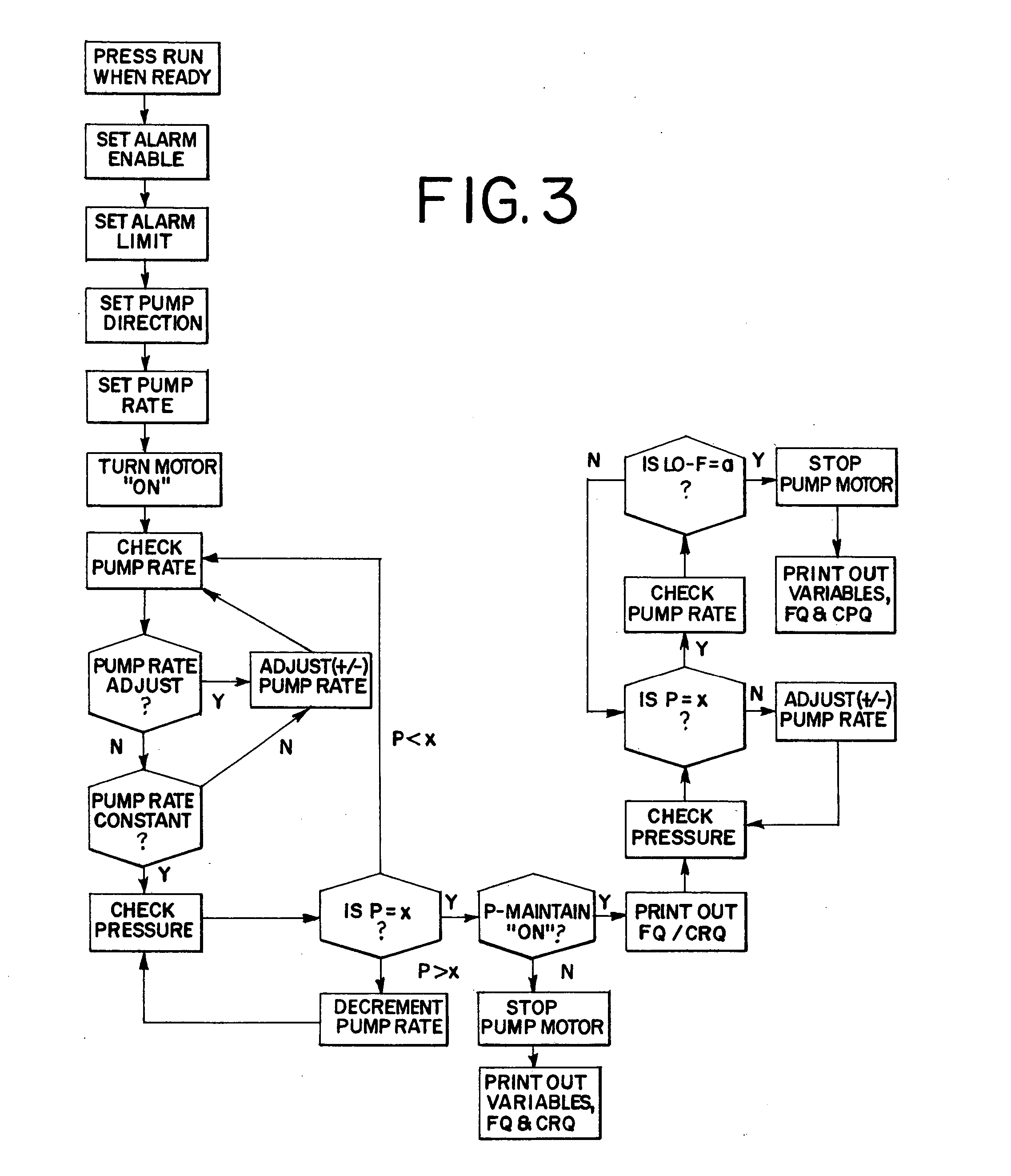
[0088] Constant rate filtration with a constant pressure condition was carried out on a unit generally in accordance with FIG. 1. A constant pump rate of 15 ml / min was implemented until a backpressure of 20 psi was reached. At this point, the processor-controlled pump unit switched automatically to a constant pressure delivery by modulating the pump output in order to maintain the 20 psi pressure level. An operator-defined low flow alarm setting of 1.0 ml / min was reached, and the unit automatically stopped pumping to complete the processing.

[0089]FIG. 5 provides data from this dead end filtration approach with an MFS cellulose acetate membrane filter having a 0.45 micron porosity and a filter area of 1.73 square centimeters. A dilute milk solution as described in Example 1 was used as the surrogate protein solution. The area under the pump rate versus time curve of FIG. 5 represents the total, collected filtrate rate, which was 136 grams or 7.86 grams per square centimeter of filte...

example 3

[0092] The procedure of Example 2 was generally followed, but on a larger scale. A 300 square centimeter SARTOBRAN™ 300 cellulose acetate membrane filter. This had a porosity of 0.45 microns for the pre-filter element, followed by a 0.20 micron final filter. Distilled, deionized water was pumped through this separation unit before processing was begun. Data were generated and are reported in FIG. 6. This filtration proceeded under constant weight and then constant pressure conditions. The total filtrate weight was 2,206 grams, with the constant rate mode contributing 1,491 grams while the constant pressure mode added 715 grams.


PUM

PropertyMeasurementUnit
Fractionaaaaaaaaaa
Fractionaaaaaaaaaa
Pressureaaaaaaaaaa

Abstract

A method and system are provided for high-precision separation of pharmaceutical or biotechnology liquids. The separation can be in accordance with direct flow filtration, tangential flow filtration or preparative chromatography. Movement of the pharmaceutical or biotechnology liquid within a flow path is controlled according to a selected pattern. Selected patterns include automatically and progressively increasing the flow rate within the unit, automatically and progressively increasing the pressure within the unit or initially proceeding according to a relatively high constant flow rate and switching to a relatively high constant pressure at a time when a given parameter is attained.

Description

BACKGROUND OF THE INVENTION [0001] The invention generally relates to improved, automated liquid handling methods applicable to filtration and preparative chromatography of liquids for use in the pharmaceutical and biotechnology industries. With the invention, a variety of separation techniques are handled in a yield-enhancing automated manner. The invention enhances separation processes such as tangential flow filtration (TFF) (also called cross flow filtration), direct flow filtration (DFF) (also called dead end filtration or normal flow filtration), as well as preparative chromatography applications. [0002] In the pharmaceutical and biotechnology industries, the use of preparative chromatograpy, direct flow filtration (DFF) and tangential flow filtration (TFF), including micro-, ultra-, nano-filtration and diafiltration are well-established methods for the separation of dissolved molecules and / or suspended particulates. [0003] In direct flow filtration (DFF), a filtration device ...

Claims


Application Information

Patent Timeline
IPC IPC(8): B01D61/00
CPCB01D15/14B01D61/22B01D61/142B01D15/18B01D61/146
Inventor SCHICK, KARL G.
Owner PARKER INTANGIBLES LLC
Why Eureka
Try Eureka