
Reactive membrane process for the removal of vapor phase contaminants

Inactive Publication Date: 2006-02-09
ELECTRIC POWER RES INST INC
View PDF17 Cites 24 Cited by
  • Summary
  • Abstract
  • Description
  • Claims
  • Application Information

AI Technical Summary

Benefits of technology

[0013] In yet another embodiment, the present invention provides a method for producing a metallized membrane, comprising contacting a first side of a polymer membrane with a first solution comprising a metal; contacting a second, opposite side

Problems solved by technology

Mercury is present in flue gas generated by coal-fired power plants in very low concentrations (<5 ppb) and forms a number of volatile compounds that are difficult to remove.
Specially designed and costly emissions-control systems are required to capture these trace amounts of volatile compounds effectively.
There are, however, several disadvantages of fixed bed systems.
These beds also require significant space and are very difficult to retrofit into existing systems such as into the ductwork of power plants without major modifications.
However, the need to replenish the carbonaceous starting material and collect the spent activated material in a particulate collection device creates extra steps that consume additional resources.
Even though the sorbent can be regenerated to save costs, the regeneration process creates an extra step that consumes time and other resources to set up and maintain.
Elemental mercury is particularly difficult to remove by these conventional methods.

Method used


Image

  • Reactive membrane process for the removal of vapor phase contaminants
  • Reactive membrane process for the removal of vapor phase contaminants
  • Reactive membrane process for the removal of vapor phase contaminants

Examples


example 1

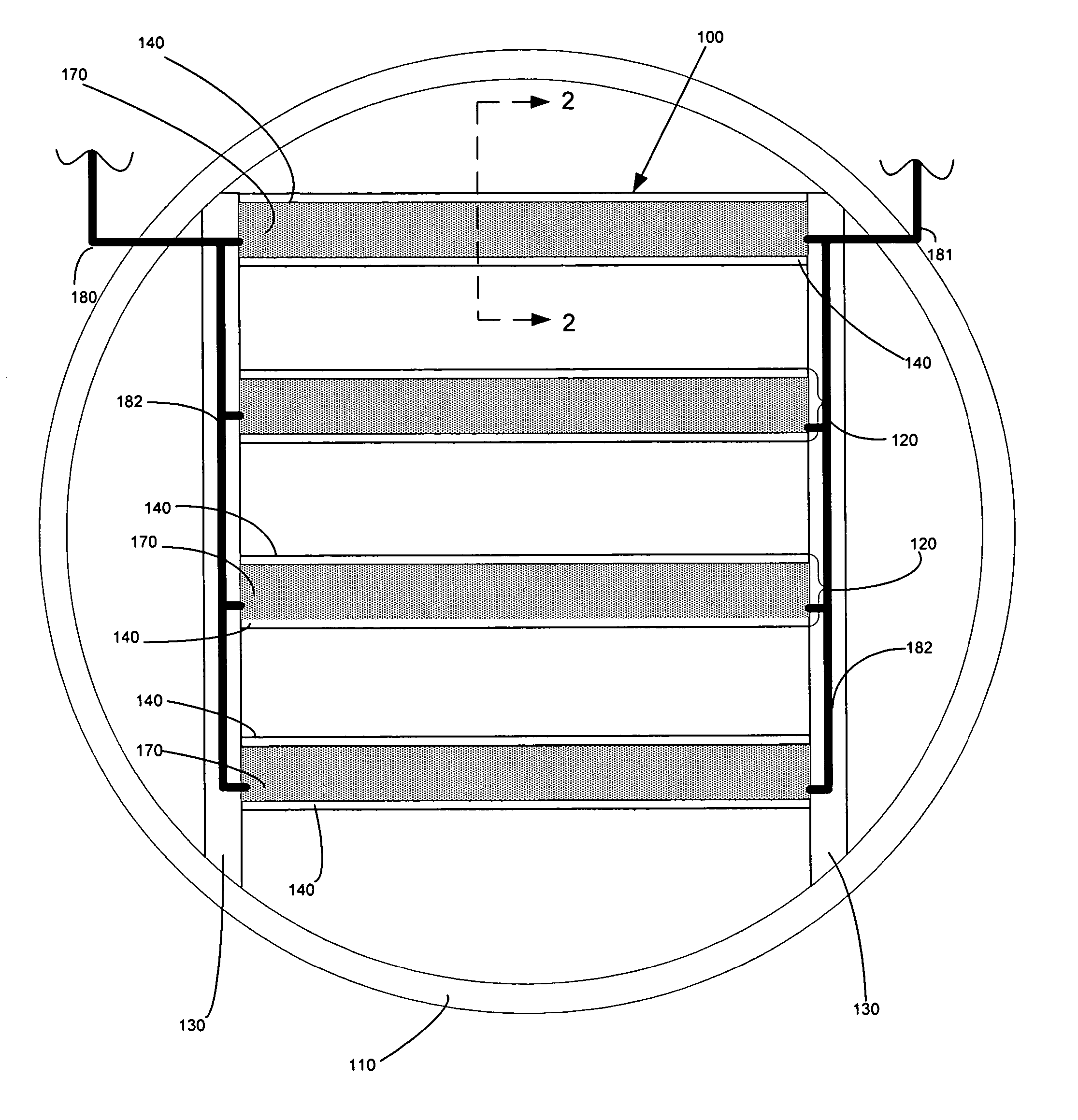
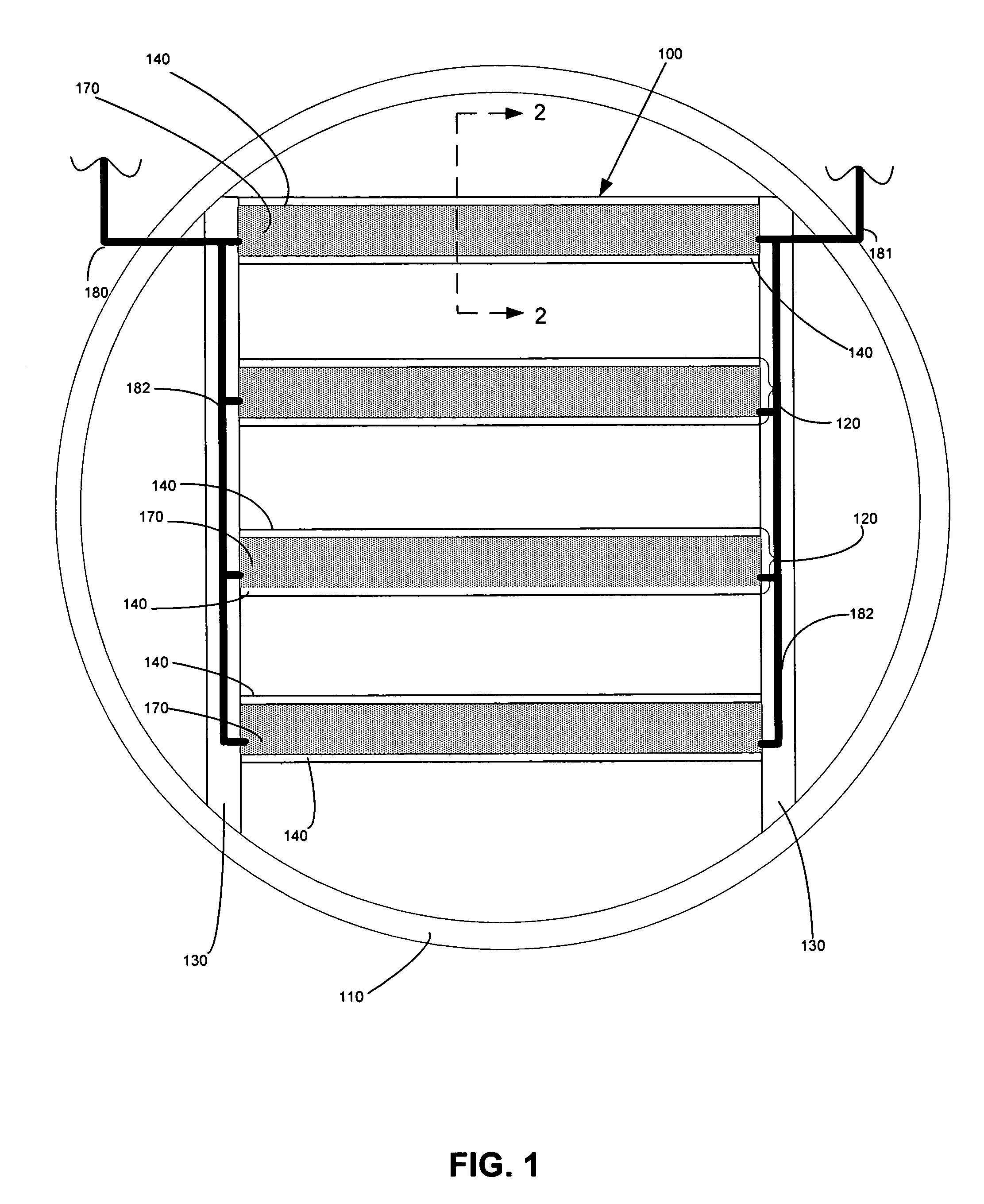
[0076] Bench-scale experiments were performed using metallized NAFION® 117 membranes and a non-metallized NAFION® 117 membranes, which is a 0.007-inch thick clear plastic sheet with good mechanical properties. The metallized membranes further comprised a gold-layered membrane and a gold-impregnated membrane, which included both colloidal gold particles and gold nanoparticle varieties. For comparison, bench-scale experiments were also performed using a gold-plated 18 gauge stainless steel screen.

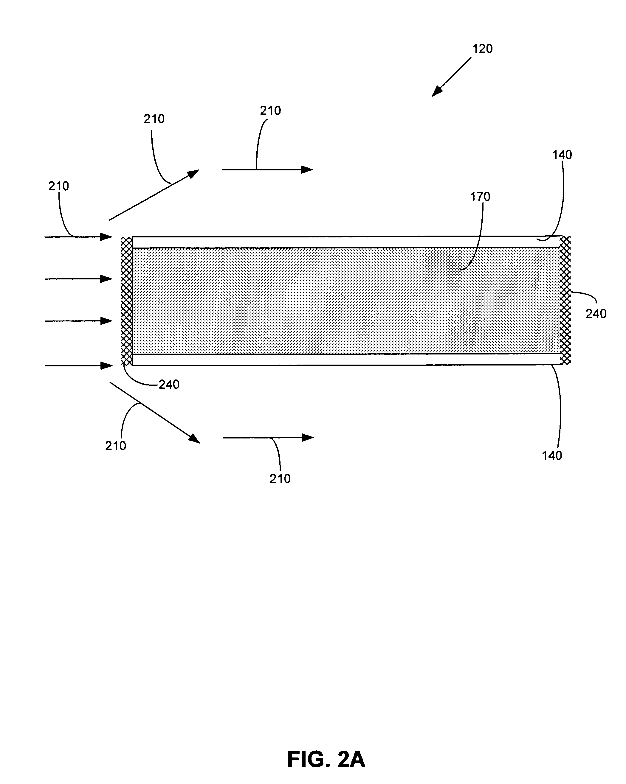
[0077] Simulated flue gas contacted one side of each membrane, and liquid was present on the opposite side of the membrane. The flue gas flow rate was 1.0 L / minute, which produced a linear velocity of 1.4 ft / sec flue gas across the membrane surface. The liquid flowed continuously over the wet side of the membrane at a flow rate of 1.34 mL / minute using a peristaltic pump. The reactor and liquid were kept in an insulated and thermostatted oven maintained at 130° F. The tests lasted between 20 ...

example 2

[0081] Additional experiments on NAFION® membranes were performed under conditions similar to Example 1, to evaluate various liquids. Table 2 summarizes the results of these experiments.

TABLE 2Elemental mercury absorption by Nafion 117(except as noted) with different liquids.Average Hg°LiquidAbsorption (%)H2O6.32.0 M HNO315.01.0 M Ferric Chloride23.01.0 M Ferric Nitrate0.00.1 M FeCl3 + 0.2 M Na3 Citrate14.00.5 M Potassium Ferricyanide1.20.05 M Methylene Blue4.61.0 M KI + 0.1 M I269.01.0 M KI + 0.02 M I255.01.0 M KI + 0.02 M I2 with 0.09 mm Nafion27.05.0 M KI + 0.05 M I247.50.625 M KI + 0.0625 M I2 in H2O-saturated16.2propylene carbonate


PUM

PropertyMeasurementUnit
Acidityaaaaaaaaaa

Abstract

Generally, the present invention provides a method and apparatus for removing a vapor phase contaminant from a gas stream, thereby reducing the concentration of the vapor phase contaminant in the gas stream. In one embodiment, the present invention provides a method for removing a vapor phase contaminant from a gas stream, comprising contacting a gas stream comprising a vapor phase contaminant with a first side of a membrane; sorbing the vapor phase contaminant using the membrane; reacting the vapor phase contaminant into an reacted form of the vapor phase contaminant; transporting the reacted form of the vapor phase contaminant through the membrane to a second side of the membrane; contacting the second side of the membrane with a liquid; and dissolving the reacted form of the vapor phase contaminant into the liquid. Methods for making a membrane comprising a metal for use in the present invention is also described.

Description

BACKGROUND OF THE INVENTION [0001] 1. Field of the Invention [0002] The present invention relates to a method and apparatus for removing vapor phase contaminants from a gas stream. More particularly, the present invention relates to a method and apparatus for the removal of vapor phase contaminants from flue gases generated by a coal-fired boiler using a membrane. [0003] 2. Description of Related Art [0004] Utility power plants are concerned about emissions of trace metals in light of the 1990 Clean Air Act Amendment (CAAA) on air toxics (Title III). Special attention has been given to mercury (Hg) in terms of its environmental release and impacts, and the Environmental Protection Agency (EPA) is closely scrutinizing sources that emit mercury. The EPA has determined that utility power plants, and specifically coal-fired power plants, are the major remaining source of mercury emissions into the air. Mercury is present in flue gas generated by coal-fired power plants in very low conce...

Claims


Application Information

Patent Timeline
IPC IPC(8): B01D53/64
CPCB01D53/229B01D53/507B01D2257/602B01D53/64B01D2251/90B01D53/56B01D61/00B01D47/00
Inventor DEBERRY, DAVID W.
Owner ELECTRIC POWER RES INST INC
Learn More