
Vapor deposited functional organic coatings

Inactive Publication Date: 2006-02-09
APPLIED MICROSTRUCTURES
View PDF9 Cites 41 Cited by
  • Summary
  • Abstract
  • Description
  • Claims
  • Application Information

AI Technical Summary

Benefits of technology

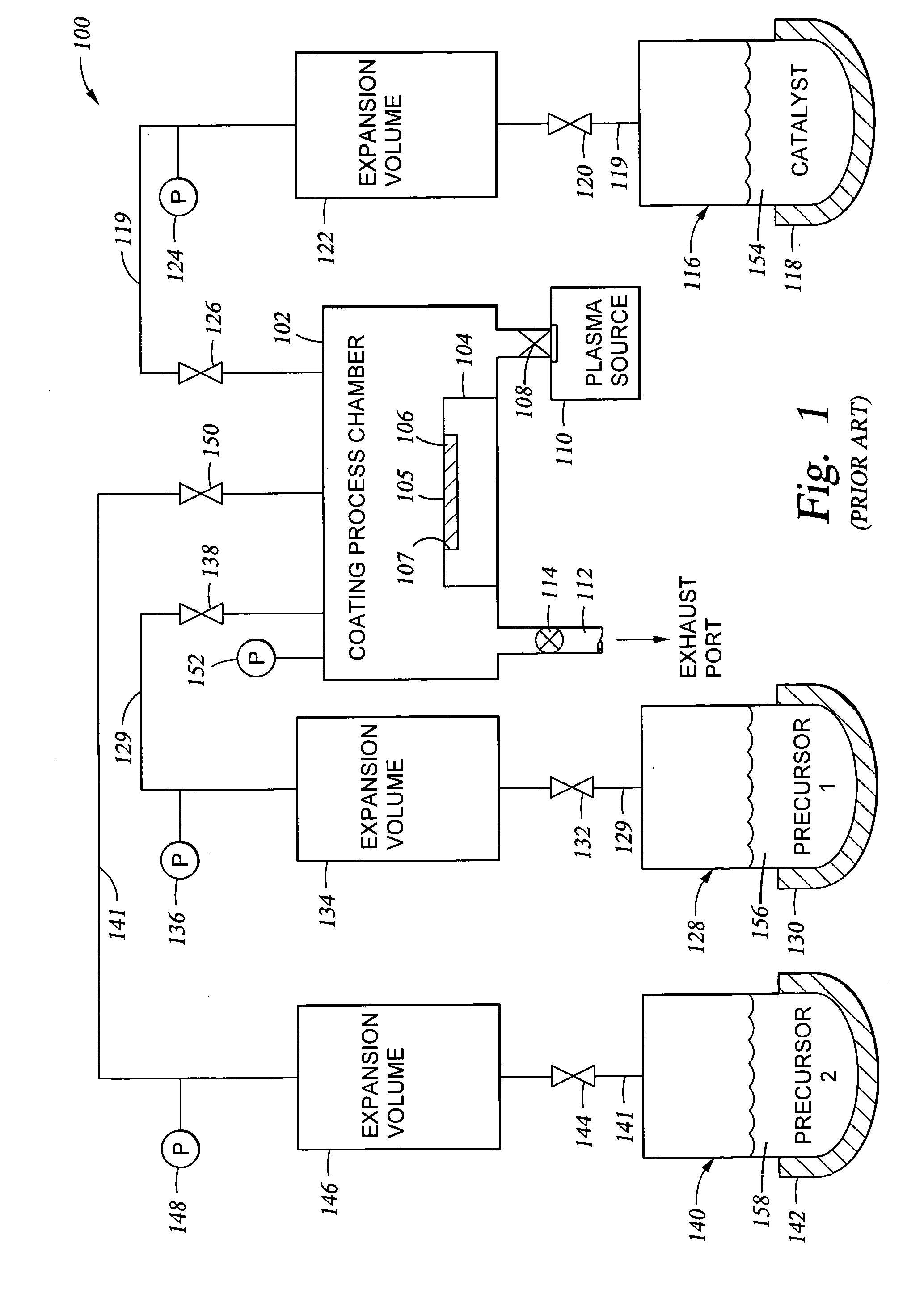
[0028] The substrate surface preparation frequently includes the use of a plasma or ozone treatment. Preferably, the plasma is a remotely-generated plasma. One preferred plasma is generated from an oxygen-containing plasma source gas. This substrate surface preparation removes any organic contamination from the substrate surface, and in some instances activates the surface for reaction. Depending on the substrate, the substrate surface preparation may not be required if the substrate surface is very clean and the substrate is treated to apply an adhesion promoting layer.
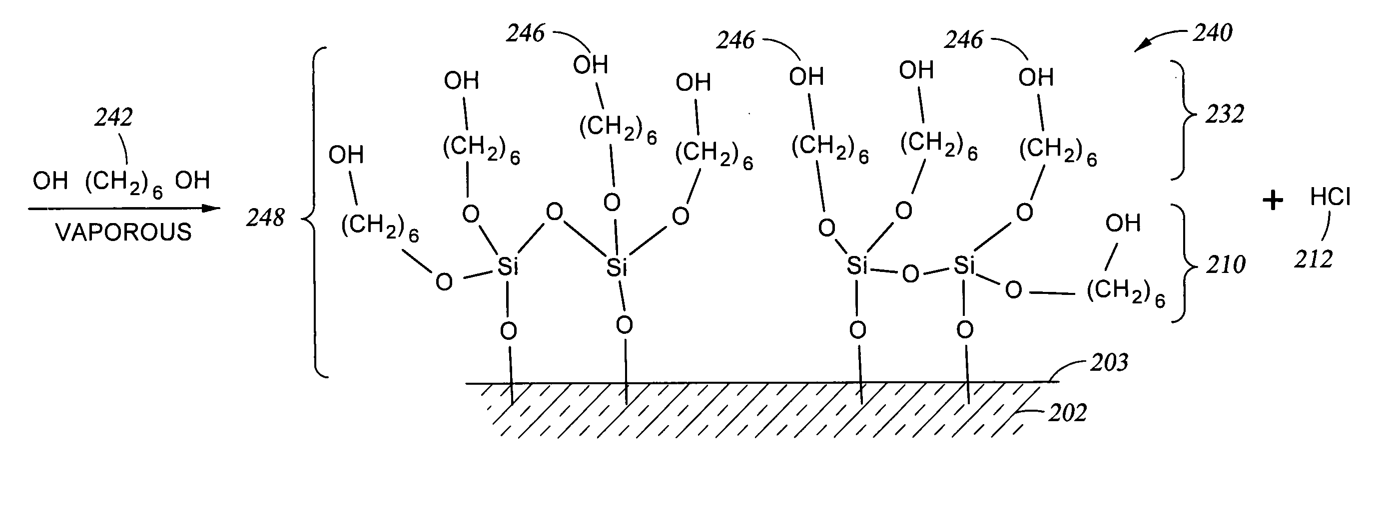
[0033] The organic layer deposition over the halogenated substrate surface is accomplished by exposing the halogenated surface to an organic molecule containing at least one nucleophilic functional group, where the organic molecule is in a vaporous state. The reaction between the halogenated surface and the organic molecule is carried out in a low pressure environment, where the pressure typically ranges from about 0.1 Torr to about 10 Torr. For example, when the organic molecule is hexanediol, the pressure in the process chamber is typically in the range of about 0.1 Torr to about 1 Torr, and more typically in the range of about 0.1 Torr to about 0.3 Torr. The reaction is typically carried out at a temperature ranging from about 25° C. to about 100° C., and more typically ranging from about 50° C. to about 60° C., for a time period ranging from about 10 minutes to about 30 minutes. Often the time period is in the range of about 15 minutes. In some instances, depending on the nucleophilic organic molecule and other process variable conditions, the process chamber may be pumped down, additional nucleophilic functional organic molecule reagent added, and the reaction process may be repeated at least once. Typically the cycle in which the process chamber is pumped down and the nucleophilic organic reagent is charged is carried out in the range of 2 to 5 times, with a 4 cycle process providing excellent results.
[0040] In instances where it is desired to create multilayered coatings, it is advisable to use oxygen plasma treatment to regenerate and to hydroxylize an oxide surface on the substrate, which oxide surface can serve as the substrate for formation of a new halogenated surface which is subsequently reacted with a nucleophilic functional organic molecule. This oxygen plasma treatment activates dangling bonds on the substrate surface, which dangling bonds can be reacted by exposure to a controlled partial pressure of water vapor to create an increased concentration of OH reactive sites on the substrate surface. The coating deposition process may then be repeated, increasing the coating thickness.

Problems solved by technology

However, at pressures above about 10 Torr reactive materials are typically in excess of the amount needed to provide the adhesion promoting layer, and reactive materials are wasted.

Method used


Image

  • Vapor deposited functional organic coatings
  • Vapor deposited functional organic coatings
  • Vapor deposited functional organic coatings

Examples


example one

Controlling the Relative Quantities of Hydroxyl and Halogen Reactive Sites on a Substrate Surface

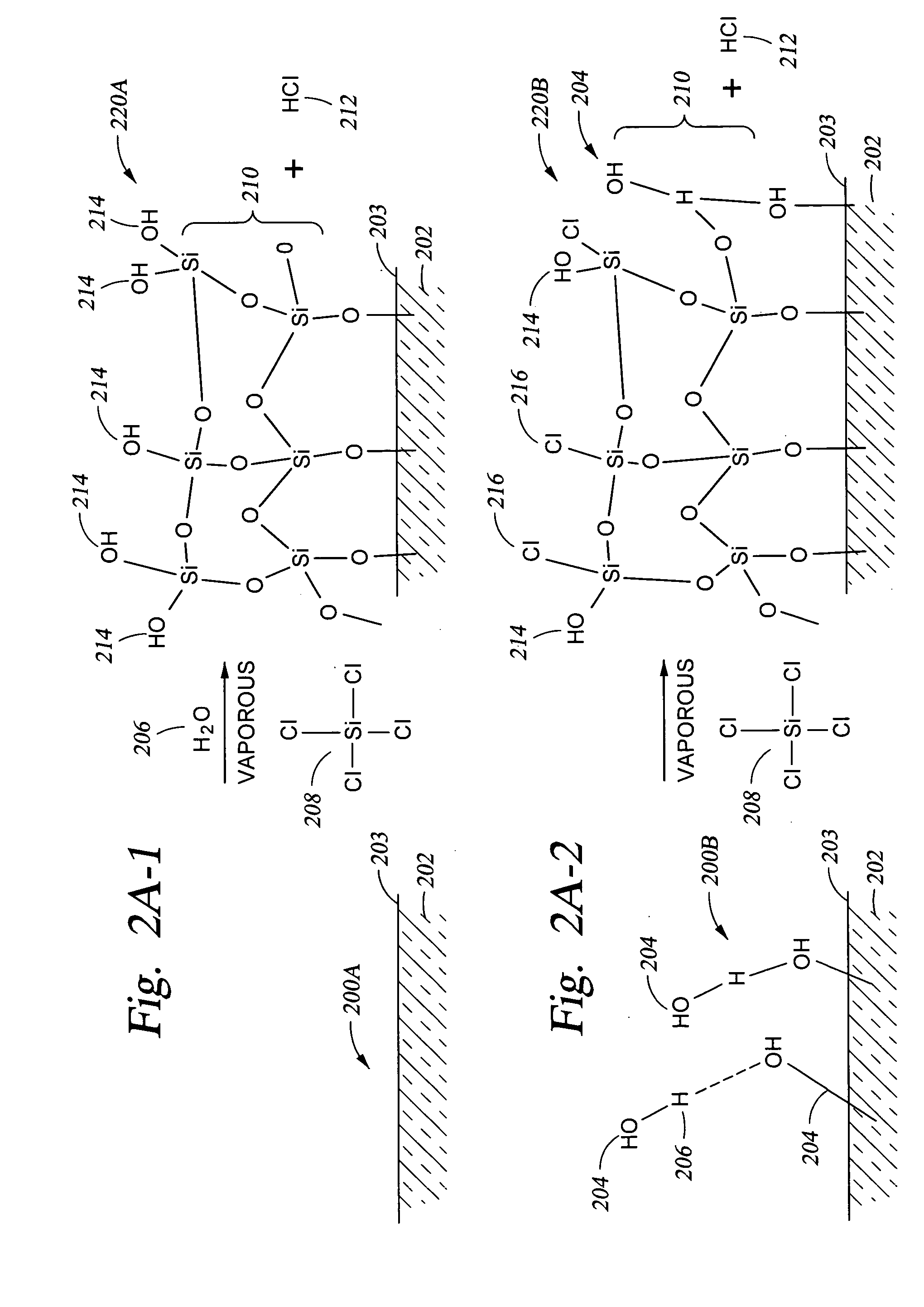
[0067] A technique for adjusting the number of OH reactive sites available on the surface of the substrate is to apply an oxide coating over the substrate surface while providing the desired concentration of OH reactive sites available on the oxide surface. In particular, in FIG. 2A-1 structure 200A which has no —OH groups 204 present on the substrate surface 203. A chlorine-containing compound, such as the silicon tetrachloride 208 shown, and water 206 are reacted with the surface 203, either in sequence (typically with the chlorine-containing compound charged to the reactor first) or simultaneously to produce the oxide layer 210 shown on surface 203 of substrate 202 and byproduct HCl 212. When the quantity of water vapor 206 (the water vapor partial pressure in the process chamber) present relative to the amount of silicon tetrachloride gas 208 (the silicon tetrachloride vapor partial...

example two

Demonstration of Control of Concentration of Halogen Reactive Sites on a Substrate Surface

[0069] In the exemplary embodiments discussed below, a silicon oxide coating was applied over a substrate. The substrate was a silicon substrate, which was first treated with an oxygen plasma in the presence of residual moisture which was present in the process chamber (after pump down of the chamber to about 20 mTorr) to provide a clean surface (free from organic contaminants). Because the substrate was silicon, this treatment also provides —OH groups on the silicon surface. A typical plasma treatment process is one carried out in the processing chamber apparatus described herein using a remotely generated plasma. The remotely generated plasma is generated from a plasma source gas containing oxygen at a volumetric percentage ranging from about 50% oxygen up to about 100% oxygen. An RF power is applied to the plasma source gas using techniques known in the art to generate a plasma. In the pres...


PUM

PropertyMeasurementUnit
Temperatureaaaaaaaaaa

Abstract

We have developed an improved vapor-phase deposition method and apparatus for the application of organic films / coatings containing a variety of functional groups on substrates. Most substrates can be coated using the method of the invention. The substrate surface is halogenated using a vaporous halogen-containing compound, followed by a reaction with at least one organic molecule containing at least one nucleophilic functional group capable of reacting with a halogenated substrate surface. The halogenation of the substrate surface and the subsequent reaction with the organic molecule nucleophilic functional group are carried out in the same process chamber in a manner such that the halogenated substrate surface does not lose its functionality prior to reaction with the nucleophilic functional group(s) on the organic molecule. Typically the process chamber is operated under a pressure ranging from about 1 mTorr to about 10 Torr.

Description

[0001] This application is related to U.S. application Ser. No. 10 / 759,857, filed Jan. 16, 2004 and entitled “Apparatus And Method For Controlled Application Of Reactive Vapors To Produce Thin Films And Coatings” and to U.S. application Ser. No. 10 / 862,047, filed Jun. 4, 2004 and entitled “Controlled Deposition Of Silicon-Containing Coatings Adhered By An Oxide Layer”, each of which is hereby incorporated by reference it its entirety.BACKGROUND OF THE INVENTION [0002] 1. Field of the Invention [0003] The present invention pertains to a method, and to the resulting structure which is created by the method, of depositing a coating from vaporous precursors in a manner such that the surface of the deposited coating is functionally designed on a nanometer scale. The method is described with reference to deposition of an organic coating where the precursor used to form the coating contains a nucleophilic functional group capable of reacting with a specially prepared substrate surface. [00...

Claims


Application Information

Patent Timeline
IPC IPC(8): C23C16/00
CPCB05D1/185B05D1/60B05D3/142C23C16/56C23C16/45525C23C16/45544C23C16/0272
Inventor KOBRIN, BORISASHURST, WILLIAM R.CHINN, JEFFREY D.NOWAK, ROMUALD
Owner APPLIED MICROSTRUCTURES
Learn More