Continuous firing furnace, manufacturing method of porous ceramic member using the same, porous ceramic member, and ceramic honeycomb filter

Inactive Publication Date: 2006-02-09
IBIDEN CO LTD
View PDF49 Cites 95 Cited by
  • Summary
  • Abstract
  • Description
  • Claims
  • Application Information

AI Technical Summary

Benefits of technology

[0012] A continuous firing furnace in accordance with a first aspect of the present invention comprises: a muffle formed into a cylindrical shape so as to ensure a predetermined space; a plurality of heat generators placed at the peripheral direction from the muffle; and a heat insulating layer formed in a manner so as to enclose the muffle and the heat generators therein, the continuous firing f...

Problems solved by technology

However, the firing method disclosed in JP-A 1-290562 (1989) mainly describes a method as to how to allow the gas to flow through the inside of t...

Method used


Image

  • Continuous firing furnace, manufacturing method of porous ceramic member using the same, porous ceramic member, and ceramic honeycomb filter
  • Continuous firing furnace, manufacturing method of porous ceramic member using the same, porous ceramic member, and ceramic honeycomb filter
  • Continuous firing furnace, manufacturing method of porous ceramic member using the same, porous ceramic member, and ceramic honeycomb filter

Examples


example 1

[0121] (1) Powder of α-type silicon carbide having an average particle diameter of 10 μm (60% by weight) and powder of α-type silicon carbide having an average particle diameter of 0.5 μm (40% by weight) were wet-mixed, and to 100 parts by weight of the resulting mixture were added and kneaded 5 parts by weight of an organic binder (methyl cellulose) and 10 parts by weight of water to obtain a mixed composition. Next, after a slight amount of a plasticizer and a lubricant had been added and kneaded therein, the resulting mixture was extrusion-formed so that a silicon carbide formed body was formed.

[0122] (2) Next, the above-mentioned silicon carbide formed body was first dried at 100° C. for 3 minutes by using a microwave drier, and then further dried at 110° C. for 20 minutes by using a hot-air drier. After the dried silicon carbide formed body had been cut, the through holes were sealed by using a sealing material (plug) paste made of silicon carbide.

[0123] (3) Successively, by ...

example 2

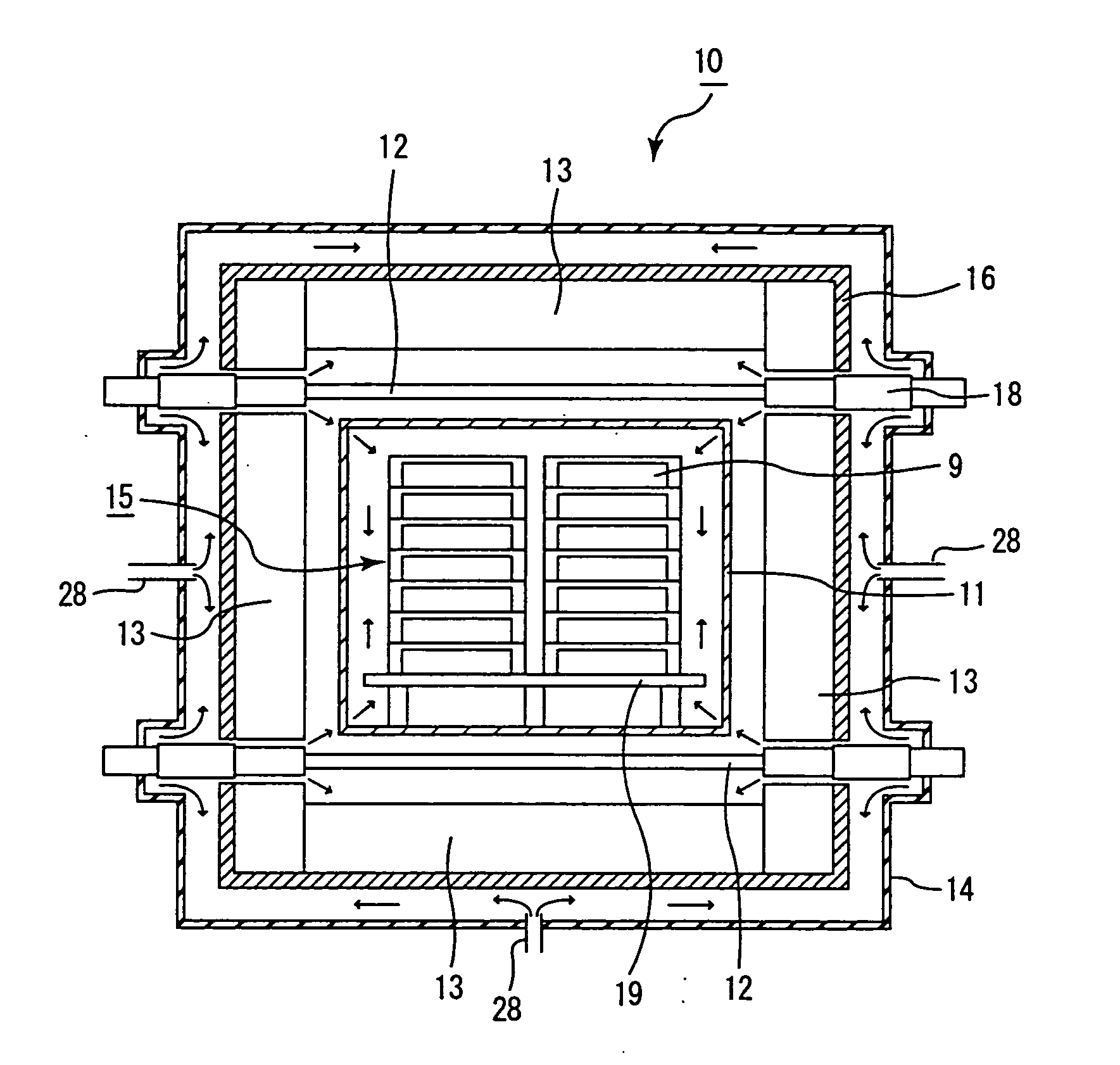
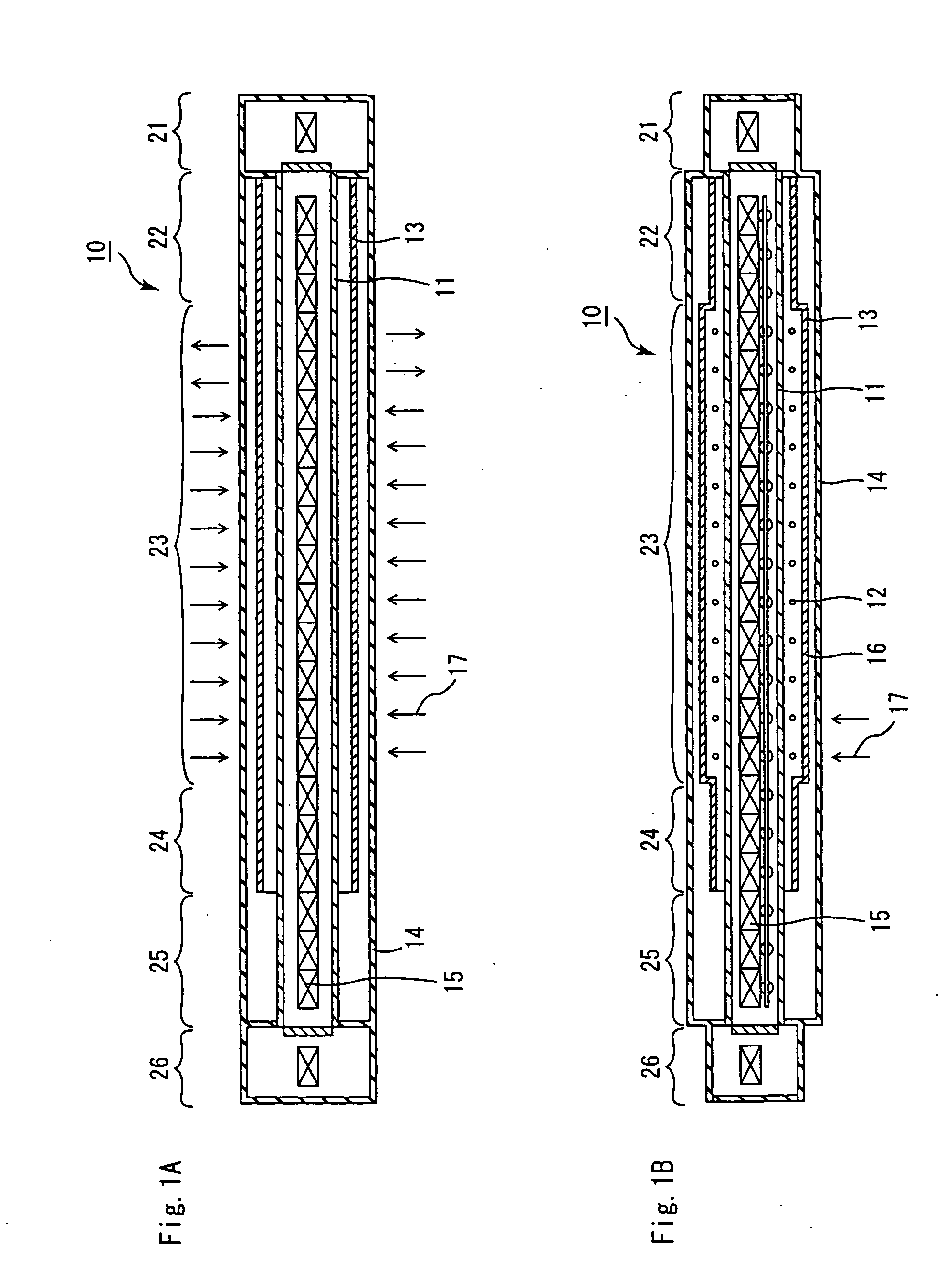
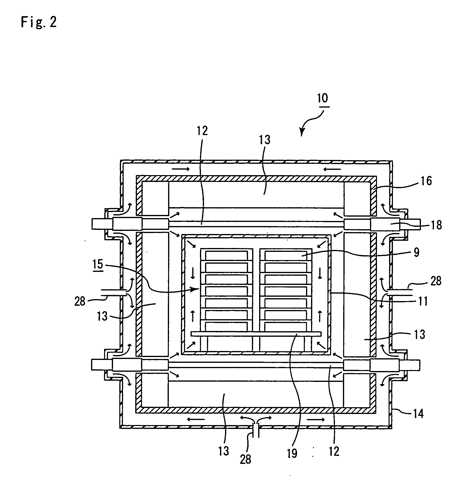
[0131] The same processes as Example 1 were carried out except that an introduction pipe 28 was formed at a position as shown in FIGS. 1A and 1B and that an exhaust pipe 29 was formed at a position (on the further outlet side from the position shown in FIGS. 1A and 1B) which has the temperature of 1800° C. inside the heating chamber 23, with argon gas introduced through the introduction pipe 28 and discharged from the exhaust pipe 29, so that a ceramic filter was manufactured, and evaluation was conducted in the same manner as Example 1.

[0132] As a result, after 50 hours of the continuous operating process as well as after 100 hours of the continuous operating process, no corrosion was found in the heater 12 and the heat insulating layer 13, and no deposited matter was found on the outside of the heat insulating layer attaching-enclosing member. Moreover, these members were made into powder and subjected to X-ray diffraction measurements; however, no peak of silicon carbide was obs...

example 3

[0134] A ceramic filter was manufactured under the same conditions as Example 1 except that a continuous firing furnace 60 using an induction heating system shown in FIGS. 4A, 4B and 5 was used, and evaluation was conducted in the same manner as Example 1.

[0135] As a result, after 50 hours of the continuous operating process as well as after 100 hours of the continuous operating process, no corrosion was found in the heat insulating layer 13.

[0136] The honeycomb structural body in which the porous ceramic members thus manufactured were used made it possible to sufficiently satisfy properties as a filter, and the honeycomb structural body, which was manufactured by using porous ceramic members that were continuously manufactured, had no change in characteristics as the honeycomb structural body.


PUM


Abstract

A continuous firing furnace of the present invention comprises: a muffle formed into a cylindrical shape so as to ensure a predetermined space; a plurality of heat generators placed at the peripheral direction from the muffle; and a heat insulating layer formed in a manner so as to enclose said muffle and said heat generators therein, said continuous firing furnace being configured such that a formed body to be fired, which is transported from an inlet side, passes through the inside of said muffle at a predetermined speed in an inert gas atmosphere and, then, is discharged from an outlet so that said formed body is fired, wherein said inert gas flows through: a space between said muffle and said heat insulating layer; and a space inside the muffle, in sequence.

Description

CROSS-REFERENCE TO RELATED APPLICATIONS [0001] This application claims benefit of priority to Japanese Patent Application No. 2004-228648, filed on Aug. 4, 2004, and PCT Application No. PCT / JP2005 / 002609 filed on Feb. 18, 2005, the contents of which are incorporated by reference herein in their entirety. BACKGROUND OF THE INVENTION [0002] 1. Field of the Invention [0003] The present invention relates to a continuous firing furnace and a manufacturing method of a porous ceramic member using the same, porous ceramic member, and ceramic honeycomb filter. [0004] 2. Discussion of the Background [0005] There have been proposed various exhaust gas purifying honeycomb filters and catalyst supporting bodies which are used for purifying exhaust gases discharged from internal combustion engines of vehicles, such as a bus, a truck and the like, and construction machines and the like. [0006] With respect to such an exhaust gas purifying honeycomb filter and the like, there has been used a honeyc...

Claims


Application Information

Patent Timeline
IPC IPC(8): F27D3/00
CPCF27B9/10F27B9/20F27B9/36F27B9/3005F27B9/2469F27D7/06
Inventor SAIJO, TAKAMITSUKASAI, KENICHIRO
Owner IBIDEN CO LTD
Why Eureka
Try Eureka