Apparatus for generating light in the extreme ultraviolet and use in a light source for extreme ultraviolet lithography

a technology of extreme ultraviolet light and apparatus, applied in the direction of x-ray tubes with very high current, lasers, photometry, etc., can solve the problems of poor efficiency in converting electricity into light, high cost of types, and high cost, and achieve the effect of high mean power

Inactive Publication Date: 2006-02-23
COMMISSARIAT A LENERGIE ATOMIQUE ET AUX ENERGIES ALTERNATIVES +1
View PDF13 Cites 52 Cited by
  • Summary
  • Abstract
  • Description
  • Claims
  • Application Information

AI Technical Summary

Benefits of technology

[0013] An object of the present invention is to remedy the drawbacks of the prior

Problems solved by technology

European patent document EP 1 319 988 A2 proposes combining a plurality of EUV sources so as to obtain a source of higher power, however solutions of that type greatly increase cost.
That gives rise to a laser that is complex, expensive, and generally presenting poor efficiency in converting electricity into light.
However, that

Method used


Image

  • Apparatus for generating light in the extreme ultraviolet and use in a light source for extreme ultraviolet lithography
  • Apparatus for generating light in the extreme ultraviolet and use in a light source for extreme ultraviolet lithography
  • Apparatus for generating light in the extreme ultraviolet and use in a light source for extreme ultraviolet lithography

Examples


Embodiment Construction

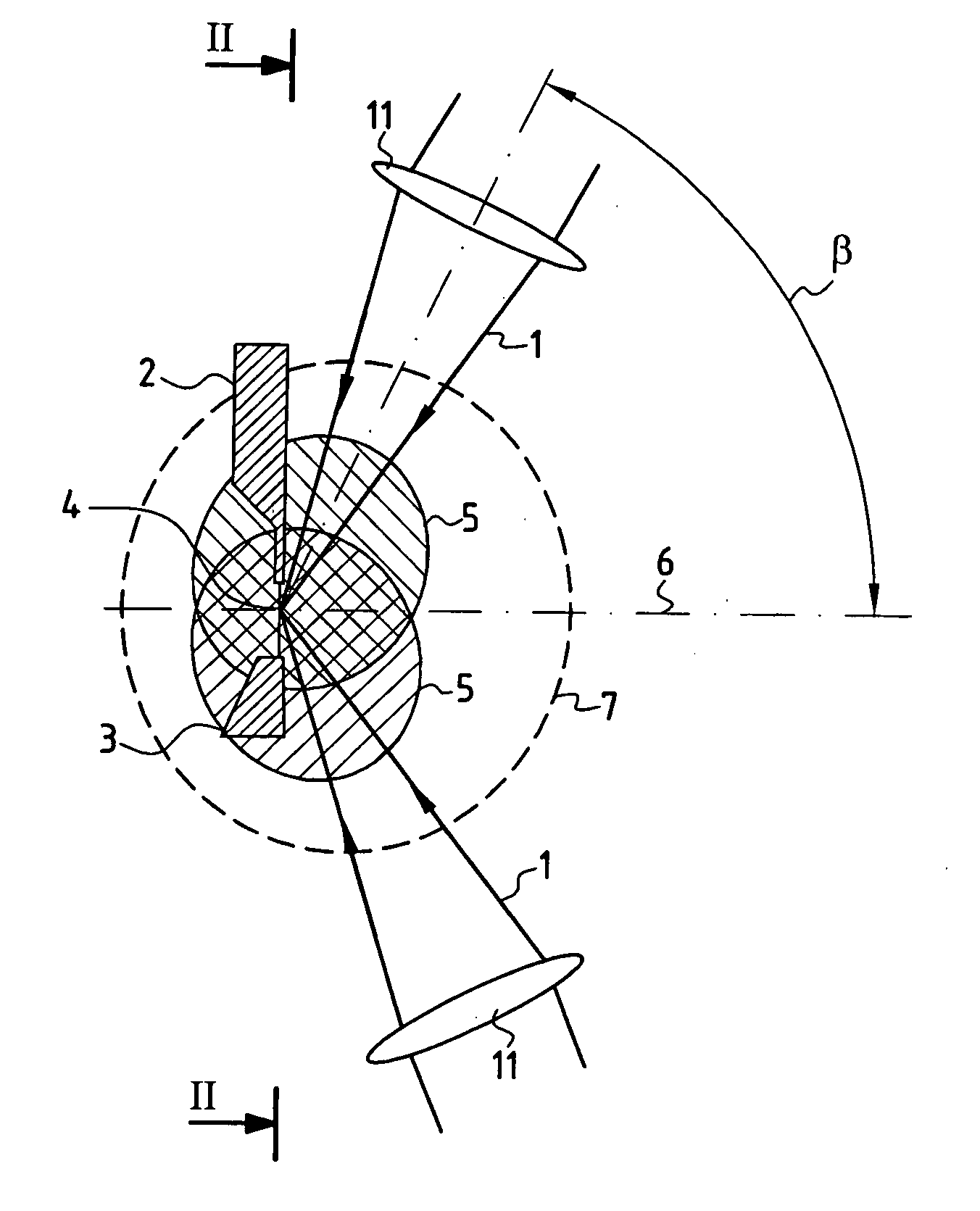
[0052]FIG. 1 shows an injector device 2 adapted to create a filamentary jet or a liquid microjet or a jet of individual droplets (e.g. of a liquefied rare gas such as xenon, or indeed metallic droplets, e.g. lithium or tin) constituting a target 4. The jet created in a vacuum by the injector device 2 is recovered by a receiver device 3.

[0053]FIG. 1 shows two power laser beams 1 focused by focusing means 11 such as lenses, diffractive optical devices (e.g. gratings), or indeed mirrors, onto the target 4.

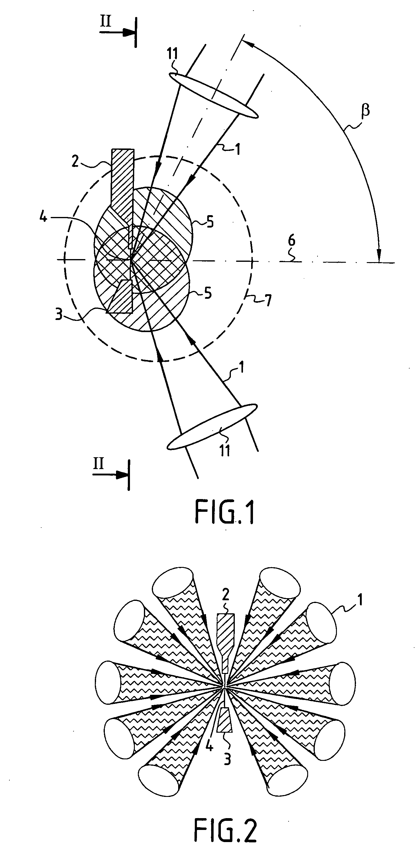
[0054] The invention makes use of a number of focused power laser beams 1 that is greater than or equal to 2. Each of the two focused laser beams 1 shown in FIG. 1 is inclined at an angle β lying in the range about 60° to about 90° relative to the mean collection axis 6 of the device. In general, a lateral approach for the laser beams 1 focused on the target 4 enables better collection to be achieved of the EUV radiation that is produced.

[0055]FIG. 1 shows the EUV emission zone 5 p...


PUM


Abstract

The device comprises a device (2) for creating an essentially linear target (4) in an evacuated space where laser beams (1) are focused, the target being suitable for interacting with the focused laser beams (1) to emit a plasma emitting radiation in the extreme ultraviolet. A receiver device (3) receives the target (4) after it has interacted with the focused laser beams (1), and a collector device (110) collects the EUV radiation emitted by the target (4). The focusing elements (11) for focusing the laser beams on the target (4) are arranged in such a manner that the laser beams (1) are focused on the target (4) laterally, being situated in a common half-space relative to the target (4) and being inclined at a determined angle lying in the range about 60° to about 90° relative to a mean collection axis (6) perpendicular to the target (4). The collector device (110) is disposed symmetrically about the mean collection axis (6) in the half-space containing the laser beams (1) focused on the target (4) and inside a conical space (8) centered on the mean collection axis (6) with a vertex situated at the target (4) and a half-angle at the vertex that is less than the angle of inclination of the focused laser beams (1) relative to the mean collection axis (6). The device is suitable for use as a source for EUV radiation in lithography for fabricating integrated circuits.

Description

TECHNICAL FIELD [0001] The present invention relates to a device for generating light in the extreme ultraviolet, and to its application to a source for lithography using radiation in the extreme ultraviolet, in particular for fabricating integrated circuits. [0002] In the description below, radiation in the extreme ultraviolet domain (typically covering wavelengths lying in the range 1 nanometer (nm) to 15 nm) is also referred to more simply as “EUV” radiation. STATE OF THE PRIOR ART [0003] For several tens of years, optical lithography has dominated the fabrication of integrated circuits. It is by continuously evolving that that technique has been able to adapt to market requirements by producing integrated circuits of ever finer resolution. The improvement in resolution has been obtained mainly by using ever shorter wavelengths. [0004] Thus, in the 60s, at the beginning of the microelectronic period, mercury lamps were used, initially at a wavelength of 436 nm, and subsequently a...

Claims


Application Information

Patent Timeline
IPC IPC(8): H01S3/22H01S3/223G03F7/20H01S3/23H05G2/00
CPCB82Y10/00G03F7/70033H05G2/008H05G2/003G03F7/70166G03F7/70008
Inventor CHEYMOL, GUYCORMONT, PHILIPPETHRO, PIERRE-YVESSUBLEMONTIER, OLIVIERSCHMIDT, MARTINBARTHOD, BENOIT
Owner COMMISSARIAT A LENERGIE ATOMIQUE ET AUX ENERGIES ALTERNATIVES
Why Eureka
Try Eureka