
Process for controlling hydrogen partial pressure in single and multiple hydroprocessors

a technology of hydroprocessors and hydrogen partial pressure, which is applied in the direction of fluid pressure control, process and machine control, instruments, etc., can solve the problems of much more capital required than what is proposed, and achieve the effects of reducing coke formation, improving hydrogen purity, and prolonging catalyst li

Inactive Publication Date: 2006-02-23
HURT WILLIAM F
View PDF16 Cites 3 Cited by
  • Summary
  • Abstract
  • Description
  • Claims
  • Application Information

AI Technical Summary

Benefits of technology

[0011] As stated above, the present invention relates to the control of hydrogen partial pressure at the reactor inlet, which is improved and automatically controlled over time. Conventional control schemes do not take into account the importance and significance of control. Some conventional processes place emphasis on absorption of contaminants utilizing a sponge oil instead of actually controlling hydrogen partial pressure. While this method can be effective, the capital that is required is much more significant than what is proposed. By utilizing the control scheme of the present invention, the average hydrogen purity may be improved by about 10-15% over conventional control schemes. This increase in hydrogen partial pressure provides longer catalyst life, inhibits coke formation, allows for the processing of heavier feedstocks, provides higher product yields, improves product quality, and results in a measurable energy savings.

Problems solved by technology

While this method can be effective, the capital that is required is much more significant than what is proposed.

Method used


Image

  • Process for controlling hydrogen partial pressure in single and multiple hydroprocessors
  • Process for controlling hydrogen partial pressure in single and multiple hydroprocessors
  • Process for controlling hydrogen partial pressure in single and multiple hydroprocessors

Examples


Embodiment Construction

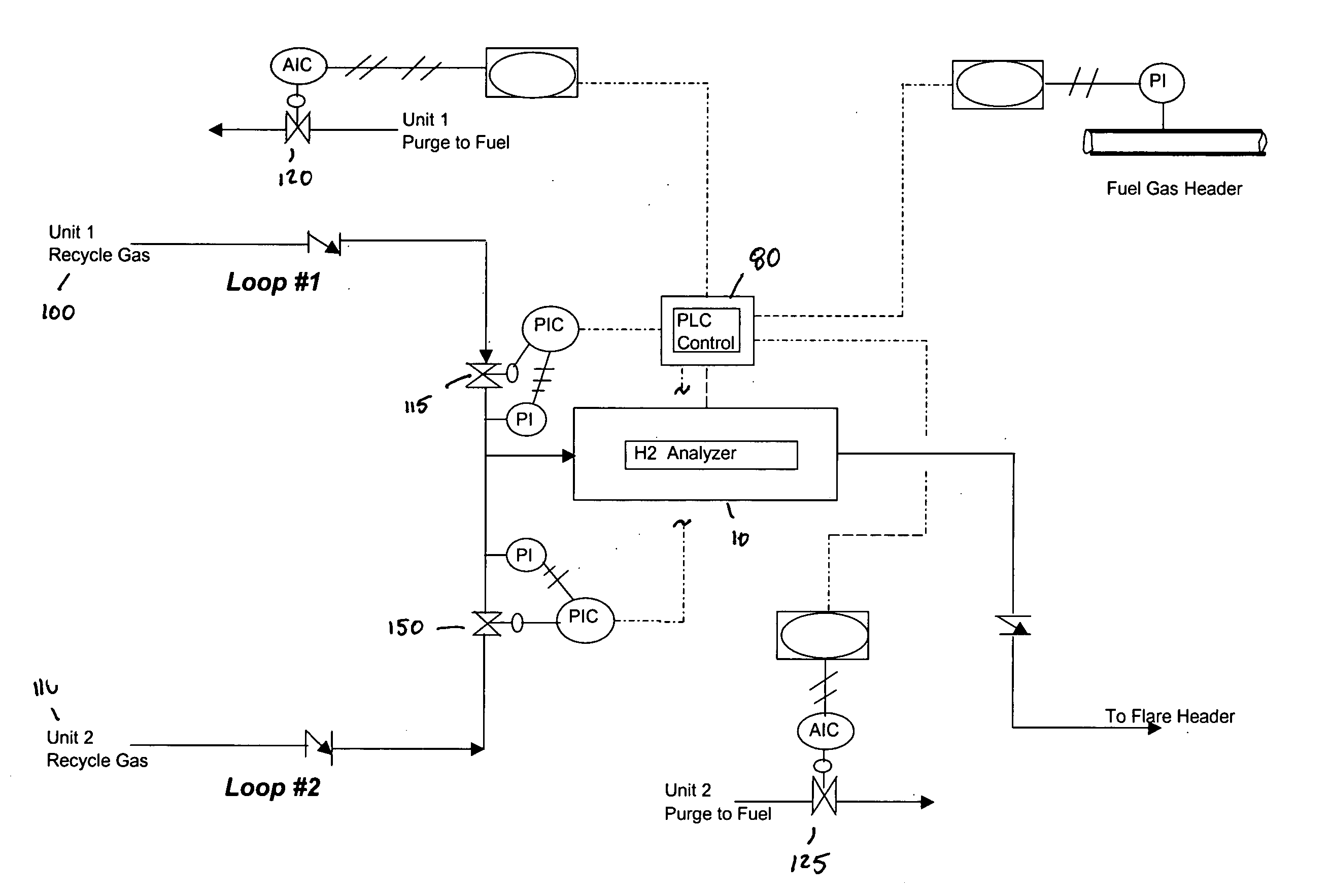
[0015] In the following detailed description of the preferred embodiments, reference is made to the accompanying drawings, which form a part hereof, and in which are shown by way of illustration specific embodiments in which the invention may be practiced. It is to be understood that other embodiments may be utilized and structural changes may be made without departing from the scope of the present invention.

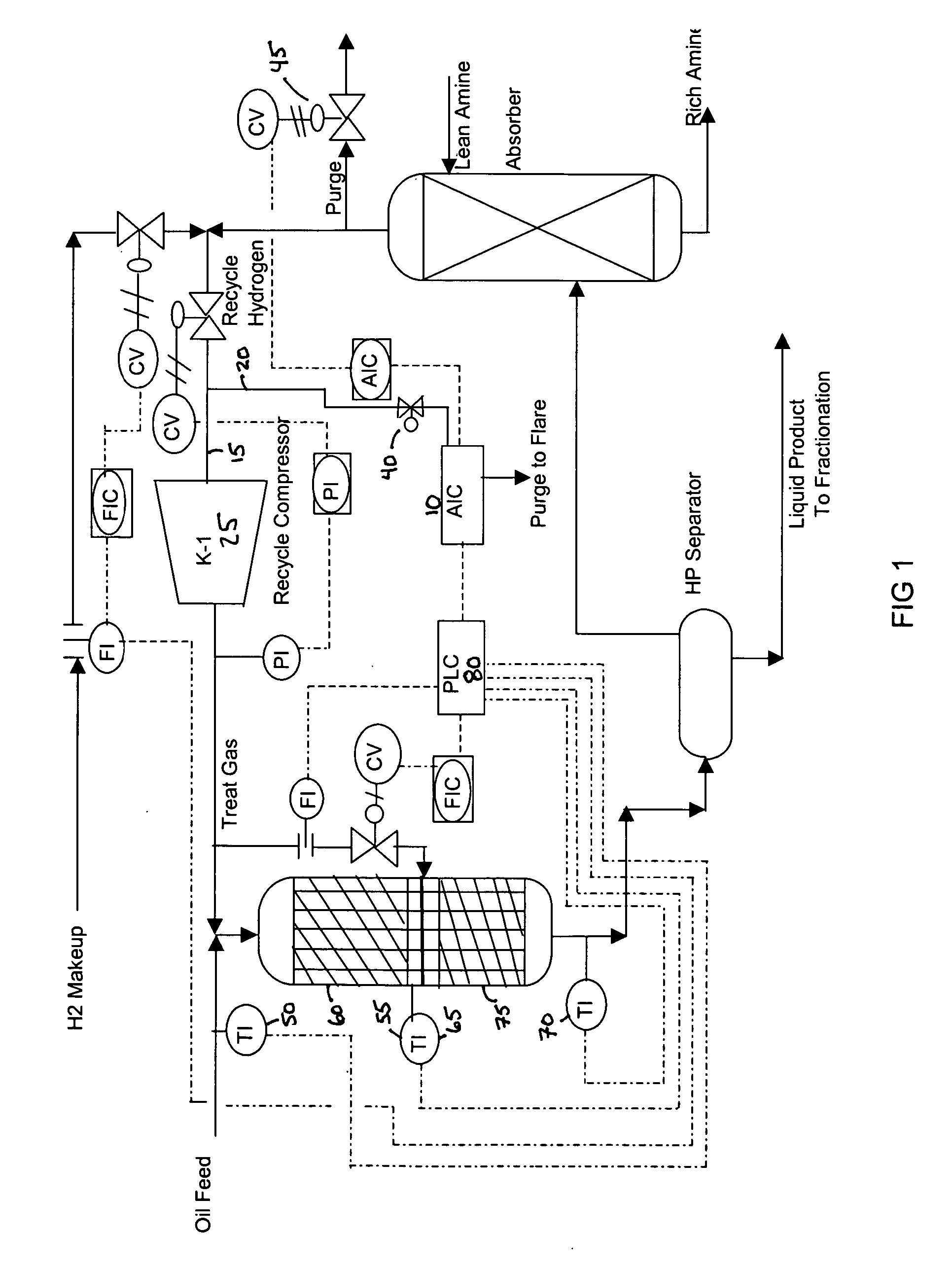
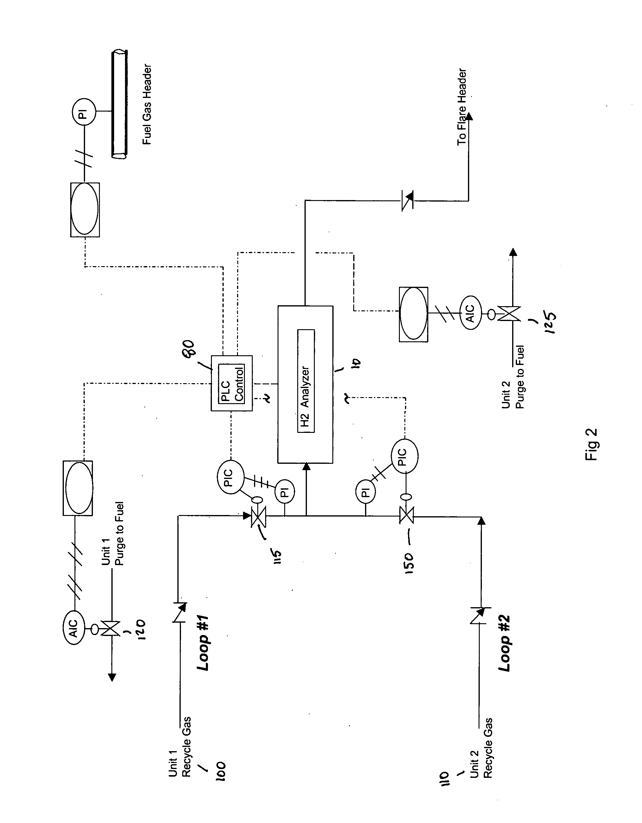
[0016] In the single unit hydrogen partial pressure control scheme, as shown in FIG. 1, a hydrogen analyzer 10 receives a sample from the hydroprocessing unit's recycle stream 15 upstream of compressor 25. A sample is drawn continuously through a small sampling line 20 (¾″ SS tubing) and the sample passes through the analyzer 10 and discharges to the plant flare system. A sampling pressure letdown valve 40 is located in the sample line 20 to reduce the pressure on the hydrogen analyzer 10.

[0017] Hydrogen purity is measured and converted into a 4 to 20 milliamp (mA) signal. The...


PUM


Abstract

A control scheme for controlling hydrogen partial pressure is provided that generally comprises a hydrogen purity analyzer that measures hydrogen purity on one or more hydroprocessing units. The hydrogen analyzer measures the purity of the treat gas, which is converted into a control signal and is transmitted to the appropriate hydroprocessing unit's purge gas controller. As hydrogen purity decreases in the hydroprocessing unit's recycle stream, the purge gas control valve opens and purges cracked gas contaminants. As hydrogen purity fluctuates, the purge gas control valve will open and close to maintain the desired purity setpoint. A programmable logic controller manages the inputs from the one or more hydroprocessing units and the signals that are transmitted to each unit's purge controller. The programmable logic controller may also be utilized to reactor hydrogen quench systems. The control of hydrogen partial pressure improves catalyst activity, hydrogen usage, and fuel efficiency.

Description

STATEMENT REGARDING FEDERALLY SPONSORED RESEARCH OR DEVELOPMENT [0001] Not Applicable FIELD OF THE INVENTION [0002] The present invention relates to the operation and control of petroleum hydroprocessing units such as, hydrotreaters, hydrocrackers, and the like. More specifically, the present invention relates to the control of hydrogen partial pressure in these units. BACKGROUND OF THE INVENTION [0003] In a hydrotreating or hydrocracking process, sulfur is removed from gasoils and distillate oils. Typical gasoil feedstocks to hydroprocessing units include heavy vacuum gas oil (HVGO), light vacuum gas oil (LVGO) and heavy coker gas oil (HCO). Typical distillate feed stocks include virgin diesel, fluid catalytic cracker (FCC) light cycle oil (LCO), light coker distillate (LCD) and heavy coker distillate (HCD). [0004] The feed to a typical hydroprocessing unit is pumped through a reactor where sulfur-containing compounds react with hydrogen to produce hydrogen sulfide (H2S), thereby l...

Claims


Application Information

Patent Timeline
IPC IPC(8): C10G45/00G05D11/00
CPCC10G49/26Y10T436/12G05D16/2046
Inventor HURT, WILLIAM F.
Owner HURT WILLIAM F
Learn More