Bleeder powered gating amplifier

a gating amplifier and bleeder technology, applied in the field of electromechanical circuitry, can solve the problems of subsequent detection, large scattering and back reflection from the atmosphere, and limited operating range of the photomultiplier tube,

Inactive Publication Date: 2006-03-02
LUDLUM MEASUREMENTS
View PDF1 Cites 23 Cited by
  • Summary
  • Abstract
  • Description
  • Claims
  • Application Information

AI Technical Summary

Benefits of technology

[0021] Additionally, the invention provides for circuit elements that inhibit spurious or premature gating during power up, enabling gating operation only after the voltage divider network reached a stable operating point.

Problems solved by technology

In many applications, the high sensitivity and limited operating range of a photomultiplier tube necessitates control of the photomultiplier tube responsivity.
When the photomultiplier tube is exposed to the strong excitation radiation used to stimulate the sample, persistent anode currents, dynode voltage depletions, and gain saturation effects interfere with the subsequent detection of the weak phosphorescence or fluorescence.
During some stages of the laser pulse travel, there is considerable scatter and back reflection from the atmosphere.
High light levels can produce sputtering of the photocathode material that can permanently damage the photomultiplier tube.
However, the switching speeds of conventional semiconductor opto-couplers, liquid crystals, mechanical shutters or choppers, and the like are generally too slow or of insufficient contrast for most detector applications.
Significant constraints and demands on the design of photomultiplier tube gating circuits are imposed by the combined requirements and / or specifications relating to the applied electrode voltage bias levels needed to adequately modulate response, switching speed, current draw, and power consumption.
Particularly, the need to apply a relatively high amplitude voltage pulse—typically on the order of ten to 100 volts—in order to sufficiently bias an electrode to suppress or enhance the secondary electron cascade between electrodes, complicates the simultaneous attainment of both fast switching speeds and low power consumption.
In fact, these two design objectives are generally conflicting, and a trade-off between high speed and power efficiency is inevitable, necessitating some design and performance compromises.

Method used


Image

  • Bleeder powered gating amplifier
  • Bleeder powered gating amplifier
  • Bleeder powered gating amplifier

Examples


Embodiment Construction

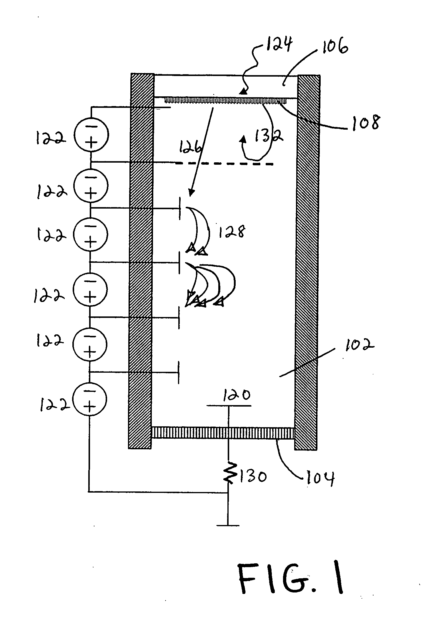
[0034] A photomultiplier tube is biased by a voltage divider network sourced by a negative high-voltage power supply. For a photomultiplier tube with several dynodes and a possibly an additional focusing electrode, as for example shown in FIG. 1, the several electrodes are appropriately biased by various voltage levels produced by the voltage divider network. This type of photomultiplier tube can be gated by applying a reverse-bias voltage pulse to the photocathode, the focusing electrode or one of the dynodes near the photocathode.

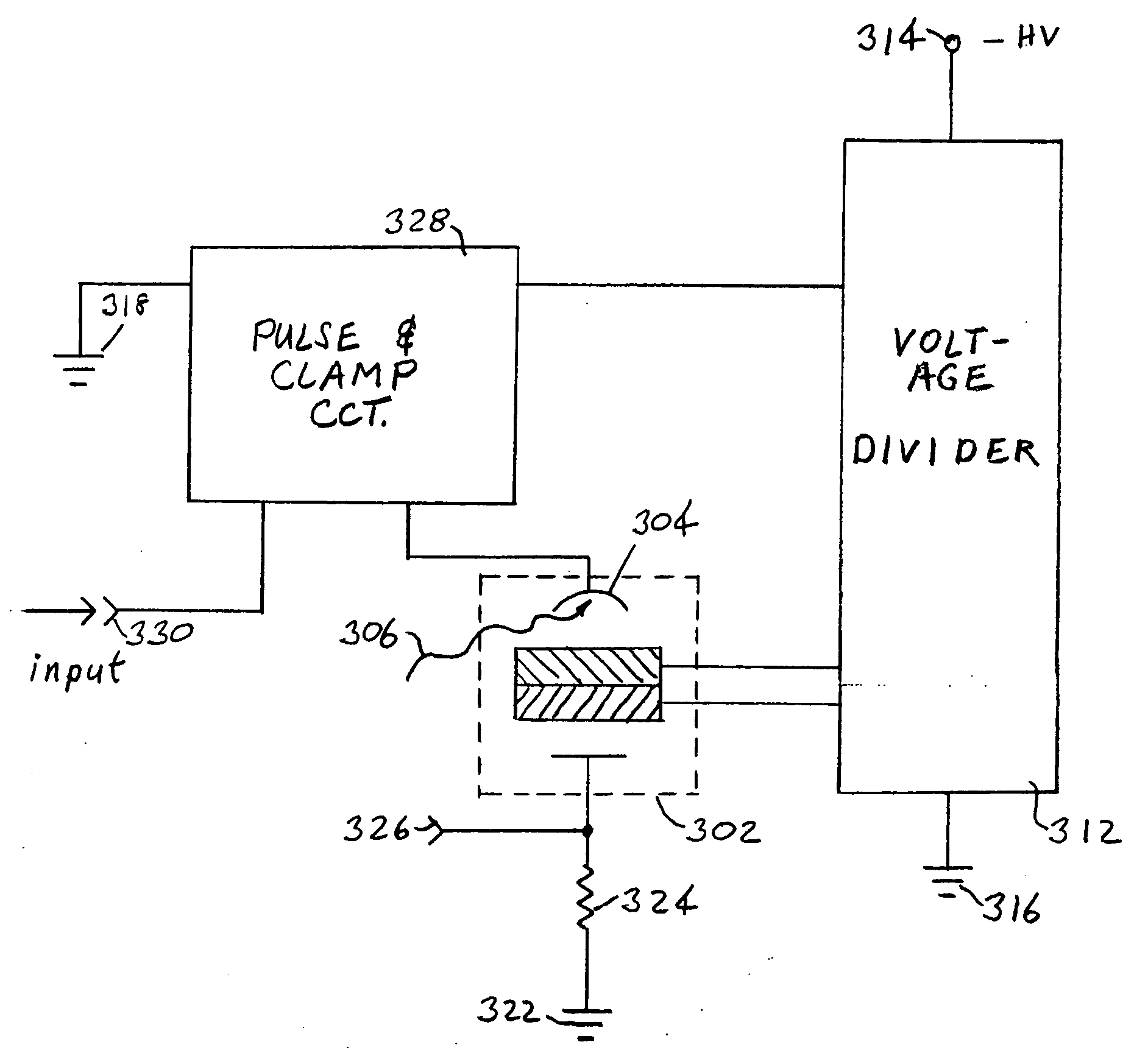
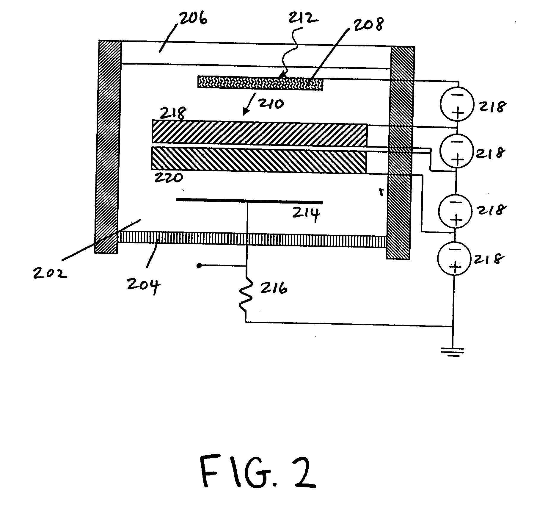
[0035] In the case of a microchannel plate type photomultiplier tube, as for example shown in FIG. 2, the voltage divider network provides appropriate voltage bias levels for the microchannel plates and photocathode. The photomultiplier tube can be gated by applying a voltage pulse to the photocathode, or to one of the microchannel plates.

[0036] The invention will be described in specifics and detail for this type of microchannel photomultiplier tube, b...


PUM


Abstract

A gating circuit switches the responsivity of a photomultiplier tube between ON and OFF states by modulating the voltage bias of the one or more of its electrodes. The gating circuit capacitively couples a voltage pulse to the photocathode or other electrode of the photomultiplier tube in response to a low-voltage gating triggering signal. The voltage divider network and high-voltage power supply used to statically bias the photomultiplier tube also power the gating circuitry and source the gating voltage pulse, thus circumventing the need for a separate high-voltage power supply. The gating circuit represents a near-inconsequential burden on the power supply, as it draws practically negligible current from the voltage divider network. The electrode gating pulse characteristics, including rise- and fall-times, voltage swing amplitude and duration, can be modified by adjusting resistor and capacitor values and Zener diode characteristics of the gating circuit and voltage divider network. The circuit can also be used to gate related devices such as microchannel plates and image intensifiers.

Description

FIELD OF INVENTION [0001] The invention relates to electronic circuitry used to control photomultiplier tubes and similar devices. More specifically, the invention concerns circuits that can be used to ‘gate’ or electronically switch photomultiplier tubes, microchannel plates, image tubes, and image intensifiers between a responsive ON state and non-responsive OFF state. BACKGROUND OF THE INVENTION [0002] Photomultiplier tubes are radiation detectors employed in diverse applications including spectroscopy, astronomy, biotechnology, remote sensing, medical imaging, nuclear physics, and laser ranging and detection. Photomultiplier tubes exhibit excellent sensitivity, high gain, and low-noise characteristics, and further, photomultiplier tubes with relatively large photosensitive areas are feasible. [0003] A photomultiplier tube is a vacuum tube device that is commonly comprised of a radiation-sensitive photocathode that emits secondary electrons in response to photons incident on the ...

Claims


Application Information

Patent Timeline
Patent Type & Authority Applications(United States)
IPC IPC(8): H01J40/14
CPCH01J43/30
Inventor THOMPSON, ROBERT C.
Owner LUDLUM MEASUREMENTS
Why Eureka
Try Eureka