
Dual-plasma fusion and fission fuel cells

a fuel cell and dual-plasma technology, applied in nuclear reactors, electrical energy generation, nuclear reactors, etc., can solve the problems of unimaginably high pressure, unmanageable, low efficiency, etc., and achieve the effect of long life and durable devices and minimal downtim

Inactive Publication Date: 2006-03-02
DAW SHIEN SCI RES & DEV
View PDF0 Cites 30 Cited by
  • Summary
  • Abstract
  • Description
  • Claims
  • Application Information

AI Technical Summary

Benefits of technology

[0048] It is an innovation of the present invention to provide an improved a dual-plasma fuel cell that can also utilize fusion / or fission reaction to provide more nuclear heating power to generate more electricity, higher current density, without fast-moving parts, and requiring less physical space than conventional fusion & fission methods.
[0052] The [GOD, II] dual-plasma fusion fuel cell and the [GOD, III] dual-plasma fission fuel cell are the long life and durable devices. By cautiously requiring radiation-prevention maintenance, they will have a minimal down-time.

Problems solved by technology

Although capable of generating electricity, problems associated with such fuel cells include a limited current density and a slower conversion rate which result in the lower efficiency and require the more physical space.
If the initial pressures are in the neighborhood of 10−4 atm, however, this resulting pressure can be unimaginably high when reaction temperature reaches millions of degree, and can not be handled with a number of known technical difficulties.
This makes the engineering work impossible, even after decade's of development.
Much attention has been paid to the design of the walls of that type reactor, which is imaged that should withstand large quantities pulsed fluxes of high-energetic particles went-off under almost vacuum state and walls are not succeeded to be stretched back and forth over a period of time which can not allow any media inside to absorb their radiant heat and to cool down the walls.
Often the daughter of a radioactive isotope is not always stable and will react to be a third nuclide, which also can be unstable.
In order for [same-charges'] fusion reaction occurring as in the conventional process, tremendous temperatures were used of today's technology and could not always do this in a controllable manner.

Method used


Image

  • Dual-plasma fusion and fission fuel cells
  • Dual-plasma fusion and fission fuel cells
  • Dual-plasma fusion and fission fuel cells

Examples


Embodiment Construction

[0053] The advantages and the present invention will become better understood with referencing to the following more detailed descriptions and claims taken in conjunction with the accompanying drawings, in which like elements are identified with like symbols, and in which:

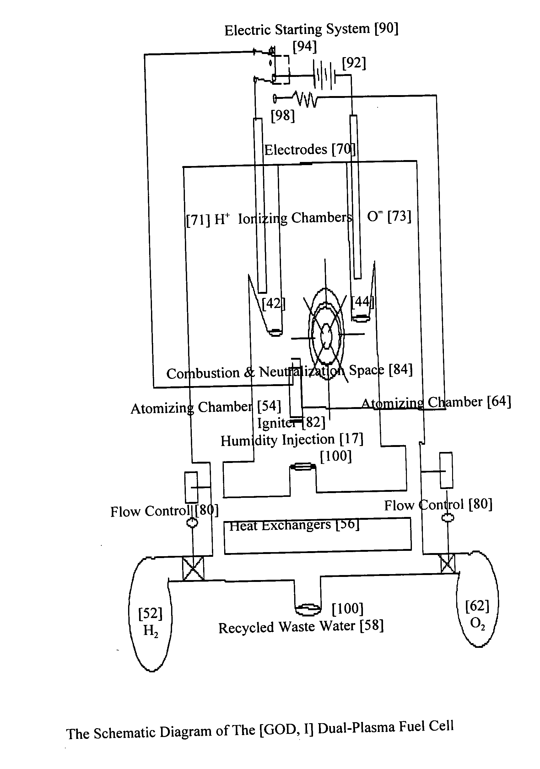
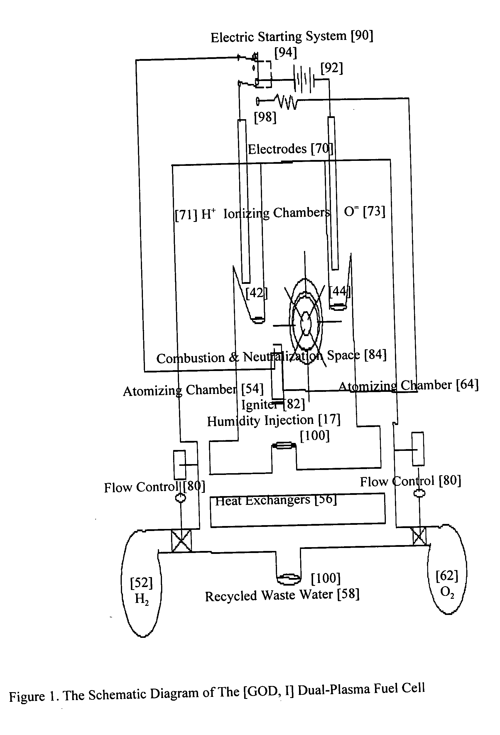
[0054]FIG. 1 is a schematic diagram of The [GOD, I] dual-plasma fuel cell according to the present invention;

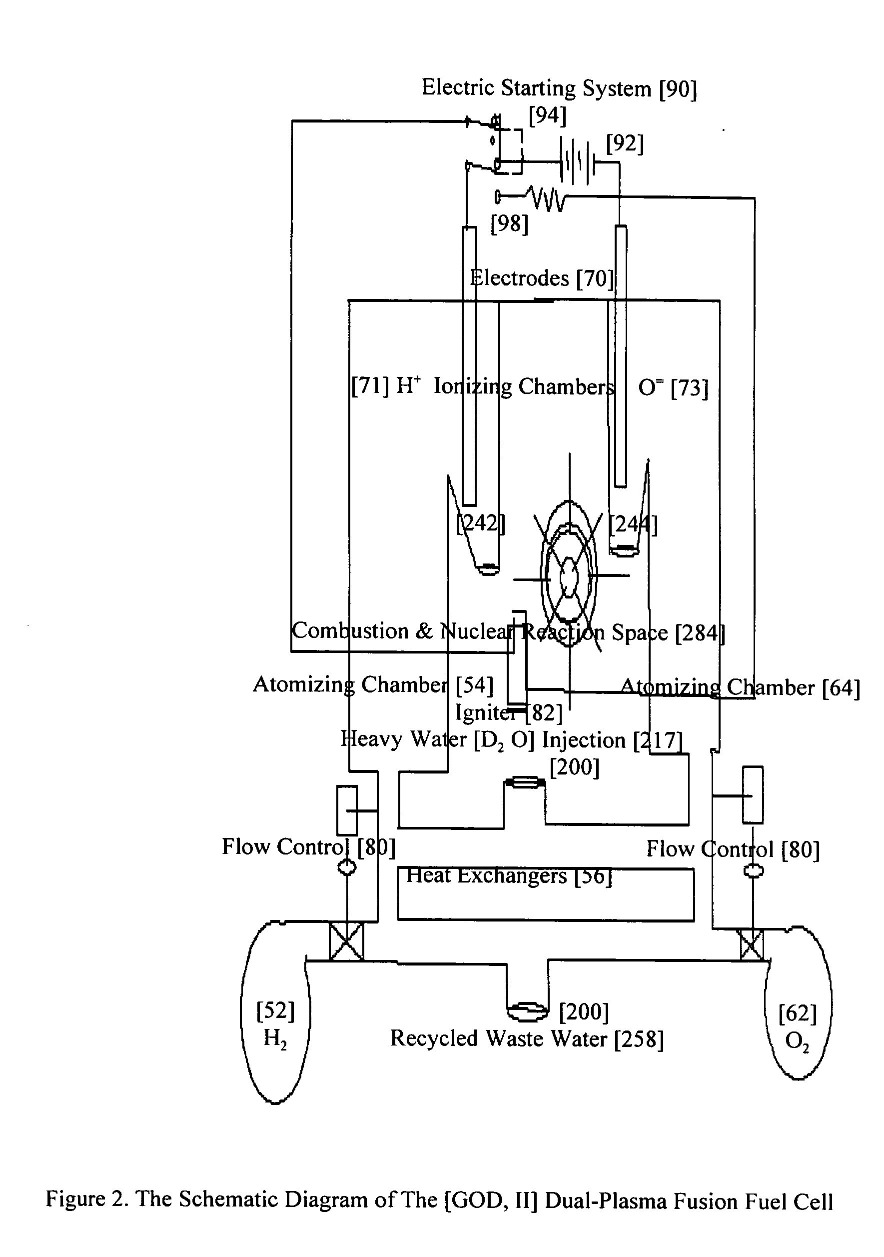
[0055]FIG. 2 is a schematic diagram of The [GOD, II] dual-plasma fusion fuel cell utilizing a fusion energy source to the electrical power according to the present invention; and

[0056]FIG. 3 is a schematic diagram of The [GOD, III] dual-plasma fission fuel cell utilizing a fission energy source to the electrical power according to the present invention; and

[0057]FIG. 4 is a schematic diagram of The [GerTh. I] dual-plasma jet thruster of by using The [GOD, I]& [GOD, II] dual-plasma fuel cells as its power sources.

DESCRIPTION OF THE PREFERRED INNOVATIONS

[0058] The best mode for describing the invention is...


PUM


Abstract

New [GOD, I], [GOD, II], & [GOD, III] dual-plasma fuel cells provide the electric start systems to start their warm-up processes, automatically. After their warm-up processes done and the operation temperatures reached, the dual-plasma fuel cells will run independently by continuously supplying fuels and moisture into the units. In dual-plasma nuclear [fusion and / or fission] fuel cells' configuration, electrical power will be generated from the nuclear-thermal-plasmas reaction by exothermal heating from combustion & nuclear reactions. With conducting high-electrons' current, the cable, loads, and electrodes are connected among one another between two plasmas' ionizing chambers for civil utility purposes. In the [GOD, II] dual-plasma fusion fuel cell, heavy water [D2O] injection into the atomizing chambers increases the plasmas heating and electrical conductivities. And the un-like charges of the heavy water's [D2O+], & [D2O−] react with plasmas' [2H+& O=] combustion heating which will induce the fusion reaction and release much more nuclear heating power for initiation of the next plasmas-generation cycle much easily. For the [GOD, III] dual-plasma fission fuel cell, fission fuels located in the combustion & nuclear reaction space through robotic movements provide additional nuclear-thermal energy that allows for initiation of the plasmas-generation process for the next cycle. For [GerTh. I] dual-plasma jet thruster, the dual plasmas are ejected to an opening end of a ‘C’ shaped magnet, and linear thrust is generated, according to the right-hand rule as in a jet thruster of propulsion for space traveling.

Description

RELATED APPLICATIONS [0001] The present invention is a Continuation in Part of U.S. Ser. No. 10 / 929,023 filed on Aug. 30, 2004 and incorporated by reference herein as if fully rewritten.BACKGROUND OF THE INVENTION [0002] 1. Field of the Invention [0003] The present invention relates generally to thermal-plasmas generation methods for power and propulsion, more particularly, to a dual-plasma fuel cell that utilize fusion or fission to provide much higher current density, with no fast-moving parts (no turbines), and require less physical space than conventional methods. [0004] 2. Background of the Invention [0005] In recent years, conventional fuel cell has developed its fuel cell as a galvanic cell in which the chemical property of a fuel is converted directly into electricity by means of electro-chemical processes. Fuel and oxygen are continuously and separately supplied to the two electrodes of the cell. The electrolyte is also diluted by the water (chemical reaction product) and m...

Claims


Application Information

Patent Timeline
Patent Type & Authority Applications(United States)
IPC IPC(8): H05H1/22
CPCF03H1/0025G21D7/00Y02E30/00Y02E30/30
Inventor SHIAO, JAMES SHIHFUSHIAO, ALBERT SHIHYUNGSHIAO, FRANK SHIHCHIANG
Owner DAW SHIEN SCI RES & DEV
Learn More