Projection optical system, exposure apparatus, and device manufacturing method

a technology of projection optical system and exposure apparatus, which is applied in the direction of photomechanical apparatus, printing, instruments, etc., can solve the problems of lens heat absorption, limited materials of lenses, and reduced throughput, so as to simplify mechanical structure, minimize the influence of coating, and easy secure space

Inactive Publication Date: 2006-03-16
CANON KK
View PDF15 Cites 25 Cited by
  • Summary
  • Abstract
  • Description
  • Claims
  • Application Information

AI Technical Summary

Benefits of technology

[0012] Accordingly, it is an exemplary object of the present invention to provide a projection optical system that can easily secure a space near a first object (e.g., a reticle), simplify a mechanical structure, and minimize an influence of a coating in a plane mirror.

Problems solved by technology

Therefore, lens materials are limited to quartz and calcium fluoride for an expected light intensity.
An optical system having many lenses made of a glass material with a large total thickness absorbs the large amount of light, and reduces the exposure dose on a wafer, causing a decrease in throughput.
The lens's heat absorption and resultant temperature rise disadvantageously fluctuate a focal position, (heat) aberrations, etc.
While the quartz and calcium fluoride lenses are viable to an exposure wavelength of 193 nm, small differences in their dispersion values have difficulties in corrections to chromatic aberrations and the correction to chromatic aberrations needs plural achromatic lenses with an achromatic surface and a small radius of curvature.
Plural achromatic lenses in the optical system will increase the total thickness of the glass materials, which enhances the problems of lowered transmittance and occurrence of heat aberration.
Calcium fluoride can hardly provide a lens with designed performance suitable for a projection optical system, and complicates a fabrication of a large-aperture lens.
This complicates color corrections, and increases the cost.
For an exposure wavelength of 157 nm, only calcium fluoride is usable for materials for a lens and only a single material has difficulties in chromatic aberration corrections.
Disadvantageously, this optical system blocks light on a pupil's central part for all the angles of view to be used (hollow illumination), and cannot enlarge an exposure area.
An attempt to enlarge the exposure area results in the undesirable expansion of the light blockage on the pupil's central part.
Japanese Patent Applications, Publication Nos. 09-211332 and 10-90602 basically use a catoptric optical system, but have difficulties in securing a sufficient width for the imaging area on the image surface, because of problems, such as deteriorated aberrations (the sum of the Petzval terms) and complicate mirror arrangements.
Even an apparatus that includes a concave mirror with a strong power mainly near the image surface as an imaging function can hardly provide a high NA.
A convex mirror arranged at a position right just before the concave mirror does not provide a sufficient image-side working distance.
However, there is a concern about the influence of the hollow illumination to the pupil on the imaging performance.
An attempt to lessen the hollow illumination to the pupil inevitably adds to the power of the mirror and enlarges a reflection angle incident upon the mirror.
According to Japanese Patent Applications, Publication Nos. 05-188298 and 06-230287, the deflected optical path complicates an apparatus's configuration.
A high NA is structurally difficult because the concave mirror is responsible for most powers in the optical elements for imaging an intermediate image onto a final image.
Since a lens system located between the concave mirror and the image surface is a reduction system and the magnification has a positive sign, the image-side working distance cannot be sufficiently secured.
Since an optical path needs to be split, it is structurally difficult to secure an imaging area width.
The insufficient imaging area width is not suitable for foot-printing in a large optical system.
Japanese Patent Applications, Publication Nos. 02-66510 and 03-282527 first split an optical path using by the light-splitter, and complicate the structure of a lens-barrel.
They need the light-splitter with a large diameter and if the light-splitter is a prism type, a loss of the light intensity is large due to its thickness.
A higher NA needs a larger diameter and increases a loss of the light intensity.
Use of a flat-plate beam splitter is also problematic even with axial light, because it causes astigmatism and coma.
In addition, asymmetrical astigmatism due to heat absorptions and aberrations due to characteristic changes on the light splitting surface complicate accurate productions of the light splitter.
Thus, both references inevitably arrange the first object surface (e.g., a reticle), a lens, plane mirror and the deflected beam close to one another, and create a problem of interference between the first object surface (e.g., a reticle) or a reticle stage and a lens or a plane mirror or an insufficient space.
However, a higher NA disadvantageously makes an overall length (or a distance from the first object to the second object) too long to correct aberrations.
The plane mirrors (reflection block) necessary to deflect light near the positions of the first and the second intermediate image cause dust and flaws to greatly affect the imaging performance of the two plane mirrors performance.
As the NA becomes higher, this problem becomes more serious: The first imaging optical system that is too responsible for a reduction magnification with a higher NA excessively increases the incident angle range upon the plane mirror, and a coating on the plane mirror causes a large difference in reflected light's intensity between p-polarized light and s-polarized light.
In addition, the first imaging optical system that is too responsible for the reduction magnification lowers an image point of the first intermediate image, and makes it difficult for the plane mirror to reflect all the light at the lowest view angle onto the second imaging optical system.
The reduction magnifications in the first and second imaging optical systems significantly affect the system's reduction magnification (where the first imaging optical system has a paraxial magnification of |β1| of about 0.438 to 0.474), and an attempt at a higher NA poses a fatal problem similar to the optical system in the former Japanese Patent Application, Publication No. 2002-83766.

Method used


Image

  • Projection optical system, exposure apparatus, and device manufacturing method
  • Projection optical system, exposure apparatus, and device manufacturing method
  • Projection optical system, exposure apparatus, and device manufacturing method

Examples


first embodiment

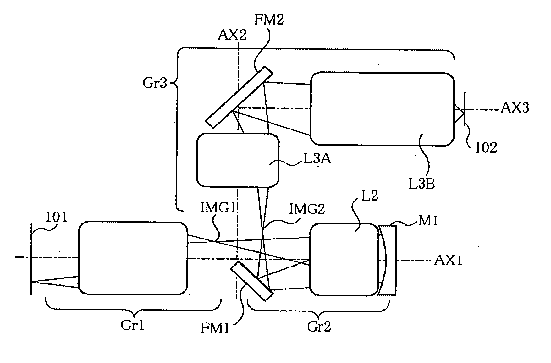
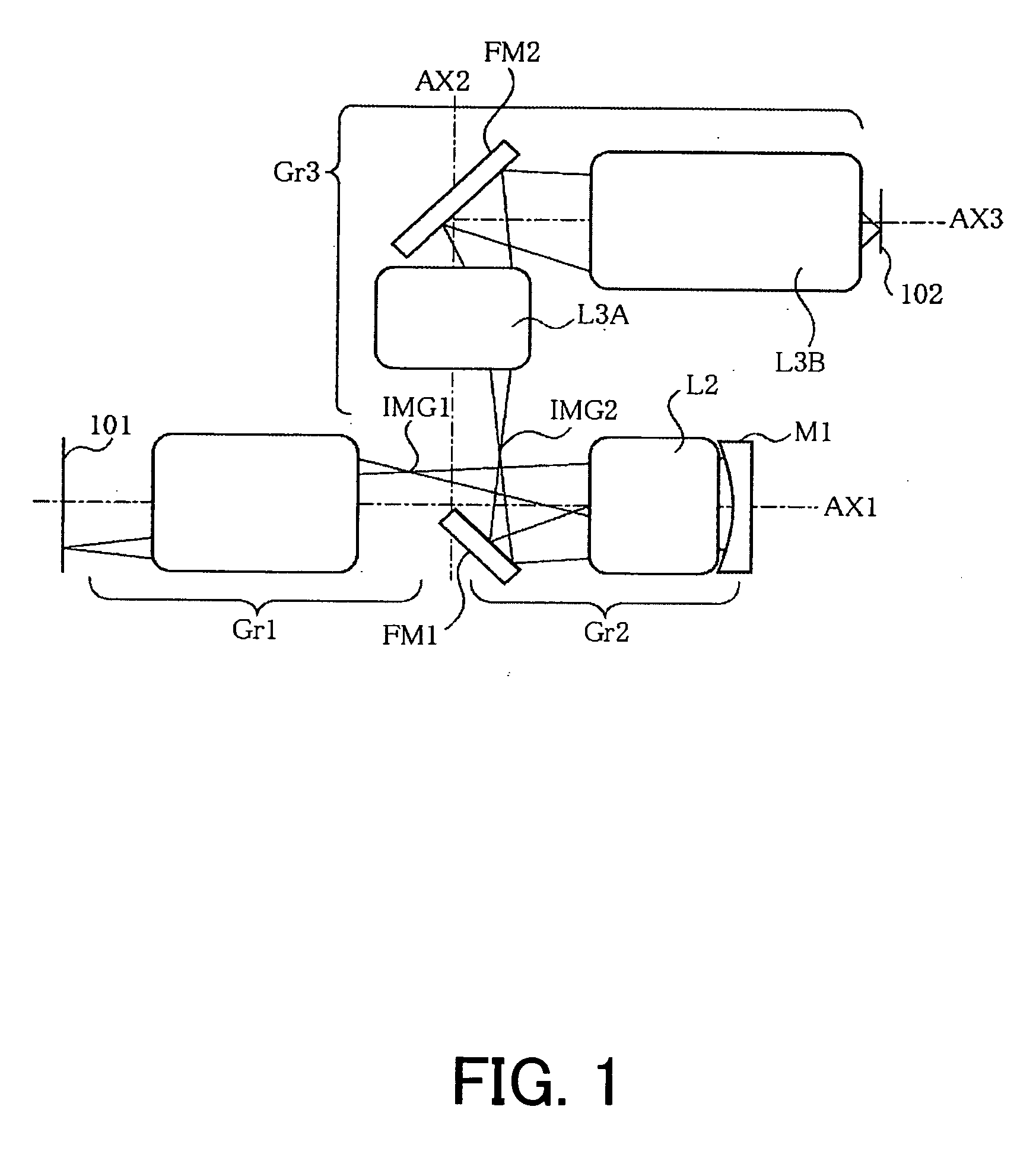
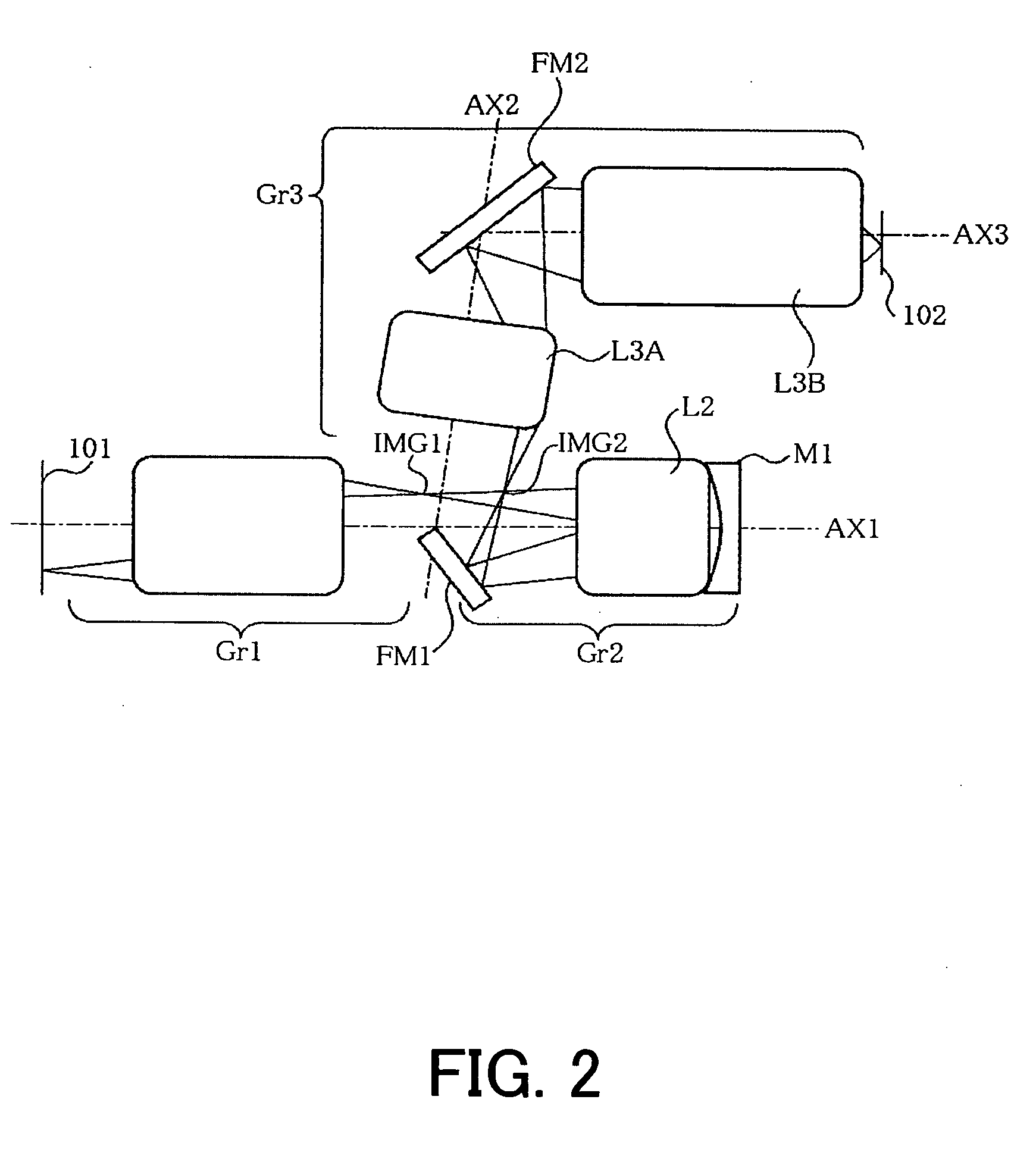
[0087]FIG. 3 shows a specific structure of a projection optical system of a first embodiment according to the present invention. This projection optical system projects a pattern on a first object (original picture having a pattern drawn on a reticle, mask, etc.) onto a second object surface, and includes first, second and third imaging optical systems. Although the first embodiment relates to a projection optical system, the present invention is not limited to this application but is applicable to optical equipments having the instant projection optical system, and an exposure apparatus. It also applies to a device fabrication method that uses an exposure apparatus which includes a projection optical system according to the instant embodiment.

[0088] The first imaging optical system shown in FIG. 3 includes, in order from the first object side, a dioptric lens group L1A having a positive refractive power and a dioptric lens group L1B having a positive refractive power. The lens gro...

second embodiment

[0101]FIG. 4 shows a specific lens configuration. The first imaging optical system includes, in order from the first object side, a dioptric lens group L1A having a positive refractive power and a dioptric lens group L1B having a positive refractive power. The dioptric lens group L1A having a positive refractive power includes, along a direction of light traveling from the side of the first object 101, a meniscus negative lens L111 with its concave surface oriented toward the first object, an approximately planoconvex aspheric positive lens L112 with its approximately flat surface oriented toward the first object, an approximately planoconvex positive lens L113 with its convex surface oriented toward the first object, a biconvex positive lens L114, and a meniscus positive lens L115 with its convex surface oriented toward the first object. The lens group L1B having a positive power includes a meniscus aspheric negative lens L116 with its concave surface oriented toward the first obje...

third embodiment

[0138]FIG. 12 shows a specific lens configuration of a third embodiment. A first imaging optical system in the figure includes, in order from the first object side, a dioptric lens group L1A having a positive refractive power and a dioptric lens group L1B having a positive refractive power. The dioptric lens group L1A having a positive refractive power includes, along a direction of light traveling from the side of the first object 101, a meniscus negative lens L111 with its concave surface oriented toward the first object side, an approximately planoconvex aspheric positive lens L112 with its convex surface oriented toward the first object side, an approximately planoconvex positive lens L113 with its convex surface oriented toward the first object side, a meniscus positive lens L114 with its convex surface oriented toward the second object side, and a meniscus positive lens L115 with its convex surface oriented toward the first object side. The dioptric lens group L1B having a pos...


PUM

PropertyMeasurementUnit
exposure wavelengthaaaaaaaaaa
relative angleaaaaaaaaaa
arbitrary angleaaaaaaaaaa

Abstract

A projection optical system for projecting an image of a first object onto a second object includes a first imaging optical system that forms a first intermediate image of the first object, and includes a lens, a second imaging optical system that forms a second intermediate image of the first object, and includes a lens and a concave mirror, and a third imaging optical system that forms an image of the first object onto the second object, and includes a lens, wherein the first, second and third imaging optical systems are arranged along an optical path from the first object in this order, and 0.7<|lβ1·β2|<3.0 is met where β1 is a paraxial magnification of the first imaging optical system, and β2 is a paraxial magnification of the second imaging optical system.

Description

[0001] This application is a continuation of prior application Ser. No. 10 / 851,869, filed May 21, 2004, the contents of which are hereby incorporated by reference in their entirety. [0002] This application claims a benefit of a foreign priority based on Japanese Patent Applications Nos. 2003-146442, filed on May 23, 2003, 2003-187469, filed on Jun. 30, 2003, 2003-189594, filed on Jul. 1, 2003, 2004-139679, filed on May 10, 2004, and 2004-139680, filed on May 10, 2004, each of which is hereby incorporated by reference herein in its entirety as if fully set forth herein.BACKGROUND OF THE INVENTION [0003] The present invention relates generally to a projection optical system, a projection exposure apparatus having the projection optical system, and a device fabrication method, and more particularly to a catadioptric projection optical system that uses a mirror for a projection optical system that projects and exposes a reticle pattern onto a wafer. [0004] The photolithography process f...

Claims


Application Information

Patent Timeline
Patent Type & Authority Applications(United States)
IPC IPC(8): G03B27/54G02B13/14G02B17/08G03F7/20
CPCG02B13/143G02B17/08G03F7/70275G03F7/70225G02B17/0892B42D1/08B42D3/12B42F5/005
Inventor KATO, TAKASHITERASAWA, CHIAKI
Owner CANON KK
Why Eureka
Try Eureka